1:32 Fairey Flycatcher
 |
 |
 |
Silver Wings 1:32 Fairey Flycatcher build guide
Instructions
A few notes on the instructions for this kit:
- The drawings labeled as "1/32 scale" on pages 6, 7 and 8 are not actually 1/32 scale.
- On page 8, the instructions list the dihedral measurement of the top wing as "13mm" when it should be 11mm. Silver Wings is aware of this and made the correction on the instructions for most kits, but be sure to check your instructions to be sure they are correct.
- Note that the landing gear drawing shown in Step 22 (page 6) is for reference only, and the actual landing gear assembly is shown in step 30 (page 9).
Parts Cleanup
As with other Silver Wings kits, parts cleanup is fairly simple, and due to the soft resin they use for their kit, a sprue cutter can even be used to snip most parts from their pour stubs. After that, a few scrapes with the Xacto knife and/or sanding stick and the part is ready for use.
With these kits, since there are no part numbers to worry about, I like to clean up all the parts and then begin the build. Any parts can be painted as appropriate after cleanup and before assembly as well. A few things to note when preparing your kit parts for use:
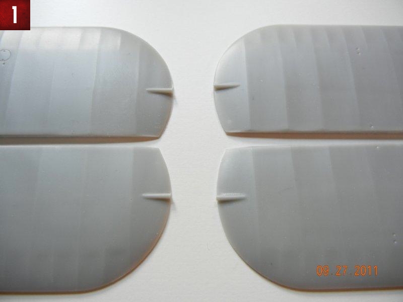
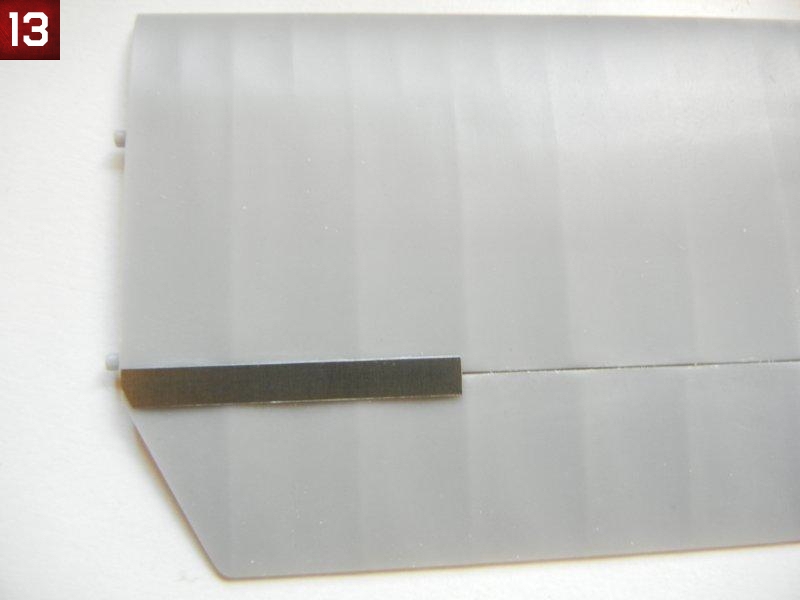
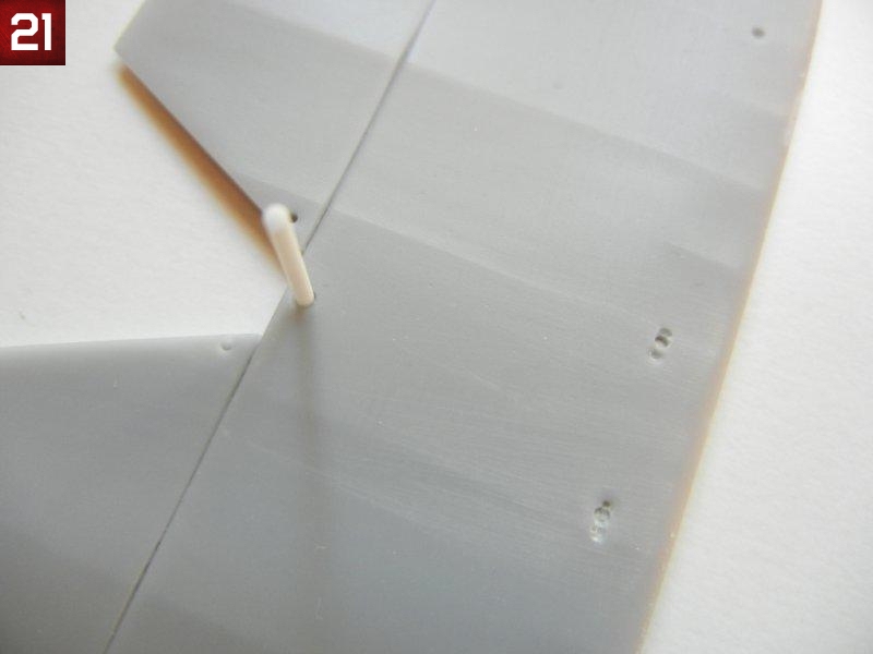
- The wings have excess resin “rods” on the upper tips (see photo 1), these must be removed as the outer wing should be smooth.
- The mating surfaces on the wing trailing edges and ailerons may require some additional cleanup to get them perfectly straight, test fit the parts as appropriate to see what cleanup may be required.
- My kit had several spare parts, including two additional cylinder heads, etc. which you may want to set aside and not clean up unless you lose a part and need them later.
- Check your fuselage framing for any breaks before you remove the pour blocks. You should repair any breaks with superglue before removing the pour blocks
- If you intend to use the kit provided cockpit frame cross brace tubes, be sure to measure them before you remove them from the pour stubs as I found I had to trim carefully in order to not end up with tubes that were too short.
- The engine block has a pour block on the backside, and you should only remove the “fins”, leaving the center round part as this will be needed to attach the engine/cowl assembly to the fuselage.
- Some of the engine cylinders may have some slight seams on the sides that require cleanup, however any that you "miss" during cleanup will likely not be visible on the finished model without searching really hard for them.
- Test fit your propeller to the engine block and enlarge the hole as necessary to achieve a good fit.
- The seat has a square that sits proud of the seat itself on the underside. This is used for positioning the seat on the support framing and should not be removed.
Interior Subassemblies
Following the instructions, complete steps 1 through 11 as indicated, notes as follows:
- Step 1: I used a paintbrush handle to bend the PE rudder straps as the PE buckle section did not want to bend as easily as the rest. Attach the completed rudder pedals to the forward floor as it will be easier to do so now than after the floor is installed in the cockpit frame.
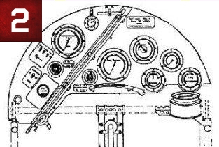
- Step 3: the instrument panel provided appears to be based on the replica Flycatcher as the "real" IP looks completely different (see photo 2 for a drawing of the actual IP in the event you want to make your own. The diagonal object is a glass tube that acts as a fuel gauge). As you cannot see much of the IP when the cockpit is completed, you may want to use the kit provided IP anyway. If you chose to use the kit provided IP, note that it is about .25mm too wide, so trim to get a good fit.
- Step 6: Test fit, but do not glue the control column to the rod/bracket, wait to finally attach these parts during cockpit assembly in Step 13. With careful cleanup, I was able to push fit the control column and bell crank to the rod/bracket without needed glue.
- Step 8: You can wait to attach the seatbelts until after the rear bulkhead is installed if you wish. I also noted that on my kit, during test fitting the rear bulkhead, even though it seemed a little wider than the cockpit frame, seemed to fit well. However, when actually gluing everything together I found it was indeed a little wide, so I recommend sanding it down slightly to match the cockpit frame width.
- Step 11: It seems to me that the guns are a little far away from the fuselage compared to available photos, so I would recommend drilling out the holes in the fuselage completely so that the attachment pins can be inserted and the distance adjusted after painting. You can also just use the gun brackets if your model will be displayed without guns, a common configuration based on period photos.
Cockpit Assembly
Cockpit assembly starts with step 12. Having built 3 Silver Wings kits thus far, I can say that this is the easiest cockpit to assemble of any of them. The fit of the cockpit assembly into the fuselage is also the best as well.
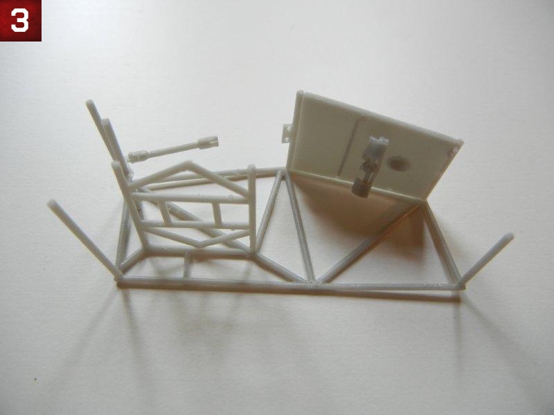
- I started my assembly by cutting the provided resin cross-braces to the appropriate lengths as indicated in step 12. Once complete, I attached the bell crank and bracket/rod to the rear 22M rod as indicated. I then attached the rods, front floorboard and "cat's cradle" to one side of the framing (see photo 3). Note that I did not attach the 22 mm cross brace that holds the rear of the fuel tank in place (shown in step 13), as this will be fitted later as test fitting showed that it would need to be placed forward of the position indicated in the instructions for the best fit.
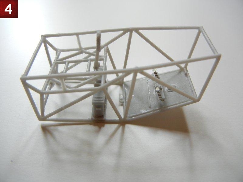
- I then attached the opposite side framing piece, and the MG ammo tray/box assembly (from step 10) and made sure everything was aligned. I also attached the control column, fitting it into the other end of the bracket/rod that was already attached to the bell crank (see photo 4).
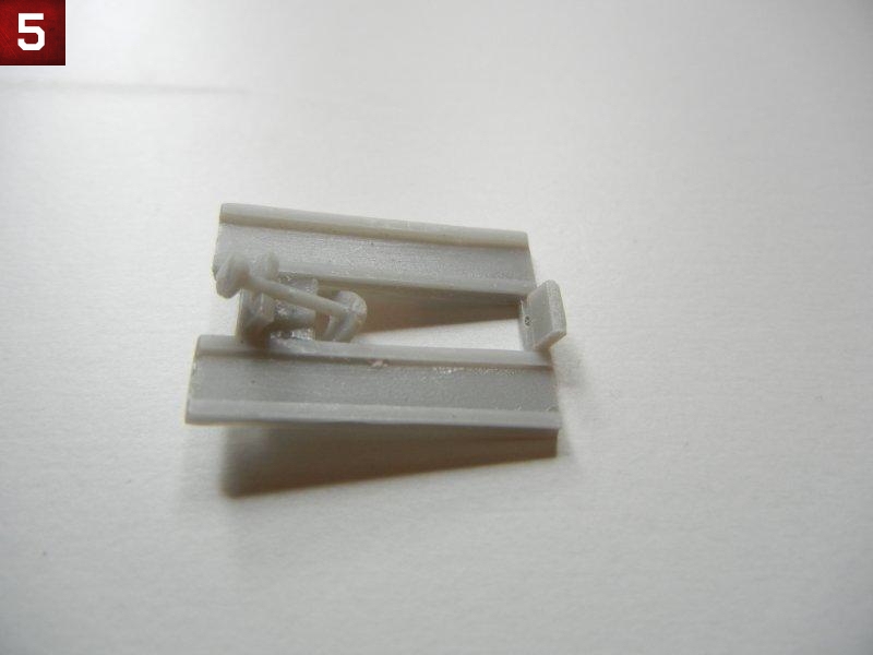
- I then dry fit the heel boards into position, however the part was too short, so I added a shim at the bottom (see photo 5) and glued the part into position. Due to the small and busy cockpit, the issue (and shim) is unnoticeable on the finished kit.
- Next, install the part from step 2 (trim control?) and pilot's seat as indicated.
- Dry fit the fuel tank to the completed cockpit frame assembly. Take note of where the rear 22mm cross brace will need to be placed, remove the fuel tank and attach the cross brace in the appropriate position.
- Attach the two ammo feed shoots in position using Gator's Grip (or other flexible glue) so that you can bend them into the correct position once the cockpit frame is installed in the fuselage halves.
- Attach the throttle and other small bits as indicated in step 14, and the throttle control cables as indicated in step 15. Once set, install the fuel tank in the appropriate position.
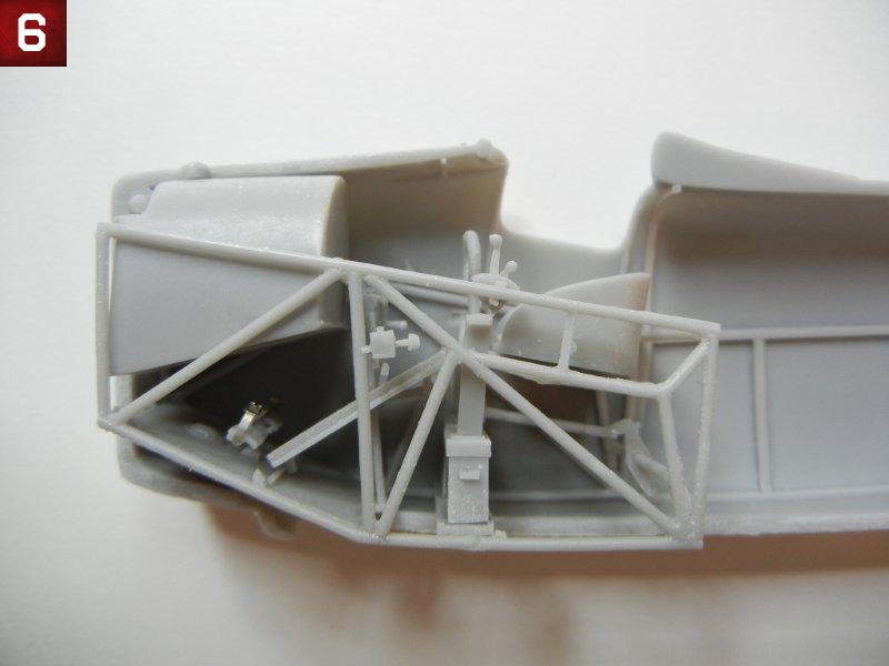
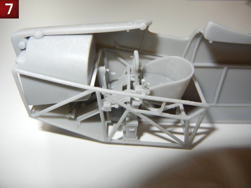
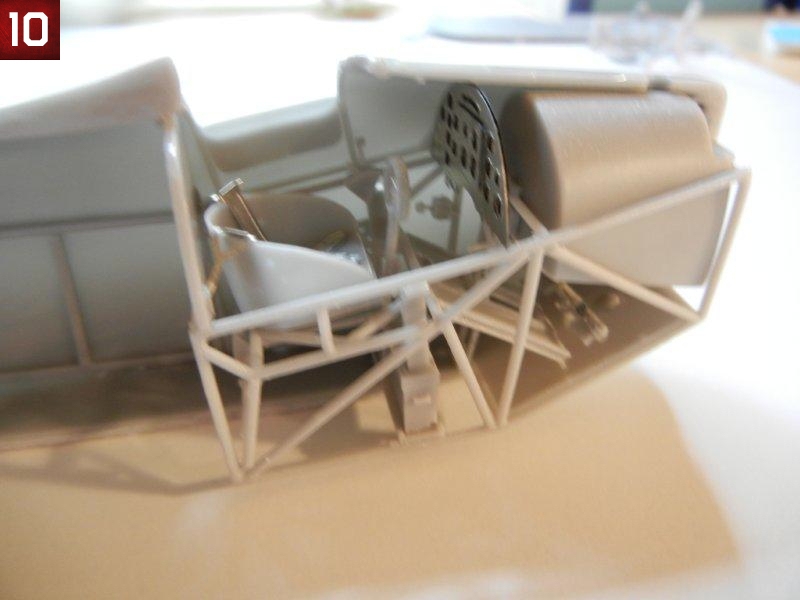
- Photos 6 and 7 show the completed cockpit assembly dry fit to the fuselage.
Fuselage Assembly
Fuselage assembly is covered by steps 21 and 22 in the instructions.
Begin the fuselage assembly be deciding if you want your pilot access doors in the open of closed position. Note that the pilot access doors slide down into the fuselage when opened. Silver Wings kindly provides two thinner doors to be used in the open position, and two thicker doors for the closed position. I opted to have the starboard access door closed, and the port access door opened.
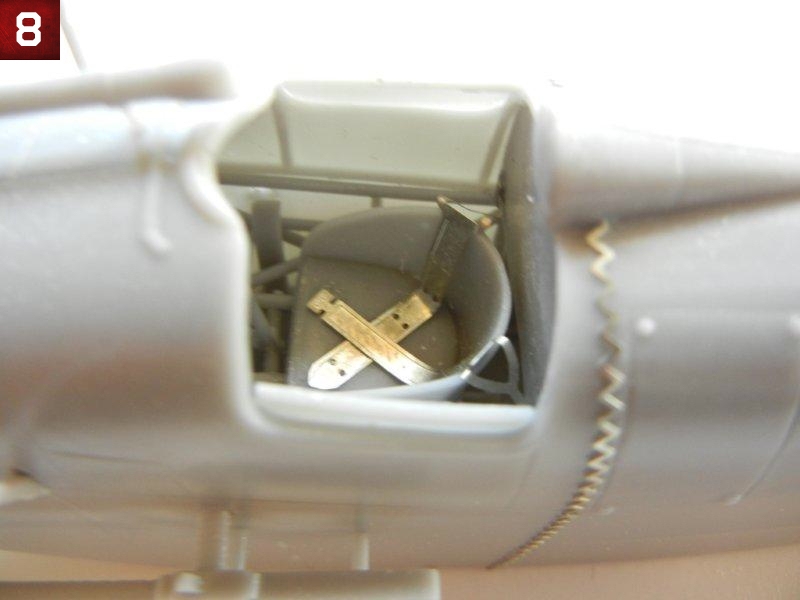
- Attach the pilot's access doors in the desired position. Photo 8 shows one open and one closed on the completed fuselage assembly.
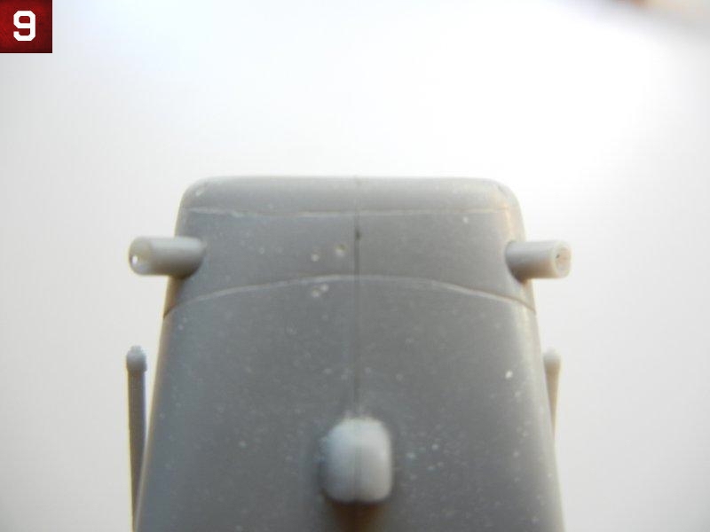
- Attach the two tubes to the lower forward fuselage as indicated. Photo 9 shows then in the installed position.
- Dry fit the cockpit and rear cockpit bulkhead into position. Once you are satisfied with the fit, remove the rear bulkhead and attach the seatbelts if you did not do so in step 8 and glue into position.
- Install the completed cockpit frame to one of the fuselage halves. Push the ammo feed chute into the correct position and secure it to the fuselage side.
- Test fit your trimmed IP (or scratch built IP) to the fuselage half, it's position indicated by the bracket on the fuselage half side framing. Glue into position when satisfied with the fit. Photo 10 shows the IP in position.
- Glue the fuselage halves together, ensuring the cockpit frame and rear bulkhead are in the correct position.
- Using a piece of rod, styrene, etc. push the remaining ammo magazine feed chute into position and glue in place.
- Once set, attach the PE stitching in the appropriate positions as indicated in the instructions. I noted that the PE parts where slightly long, so I dry fit and trimmed them as appropriate before gluing into place. As an alternative, both Archer transfers and HGW offer alternative, easy to use, stitching as well.
- I recommend waiting to install the guns, windscreen, gunsight and tailskid until later in the build.
Engine Assembly
Engine assembly is covered by steps 17 ~ 20 of the instructions.
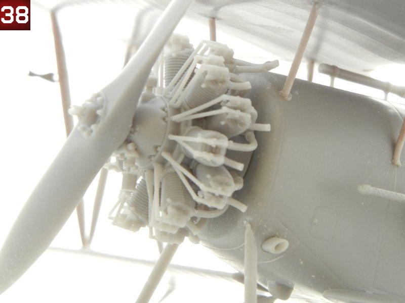
The engine of the Flycatcher is quite visible as there is no cowl, but fortunately Silver Wings gives us a beautiful rendition of the Jaguar III/IV engine. You will need to check your references to see which exhaust your kit should have and use the appropriate parts.
- I began assembly by attaching the back row of cylinders, being sure that each was facing exactly forward.
- Note that when looking at the engine from the front, the left side pushrod is attached to the engine block in front of the right side pushrod. I cut one of the pushrods and test fit it to the engine block/cylinder head in the rear (right side) position and found that it was too long, so I trimmed one to fit, and then made another 6 to match. I then attached all of the rear (right side) pushrods to the engine block/cylinder heads
- I then test fit another pushrod to the left side (front) and trimmed it to fit, and again made 6 to match. I then fit them into position as well. Note that for either side, some pushrods did require slight trimming to ensure a good fit.
- I added the front row of cylinders to the engine.
- Once set, I began attaching the intake pipes which fit to the left side of the cylinder heads (when viewed from the front) and to the mounting base. The longer leg of the intake pipes goes to the front row of cylinders. I had to bend mine slightly together to get the proper fit.
- Once finished, I repeated the process above to attach the pushrods to the front cylinders, again going left over right at the engine block base.
- I added the two parts that go on the top and bottom of the front of the engine block.
- Attach the appropriate exhaust pipes for your model.
- If using the short exhaust pipes, you may want to place the engine temporarily on the taped together fuselage to get the alignment of the two upper section exhausts correct. After that, you can attach all the small tubes pointing upwards and outwards to the remaining positions
- If using the long exhaust pipes, you can attach the collectors at this point. You can temporarily place the engine on the taped together fuselage in order to determine the length of spacing rod to attach to the exhaust pipes for mounting to the outer fuselage. I would recommend marking the position of attachment and drilling out a hole, which will allow you to attach a longer rod that can be pushed into the hole and adjusted for optimal fit during the final assembly.
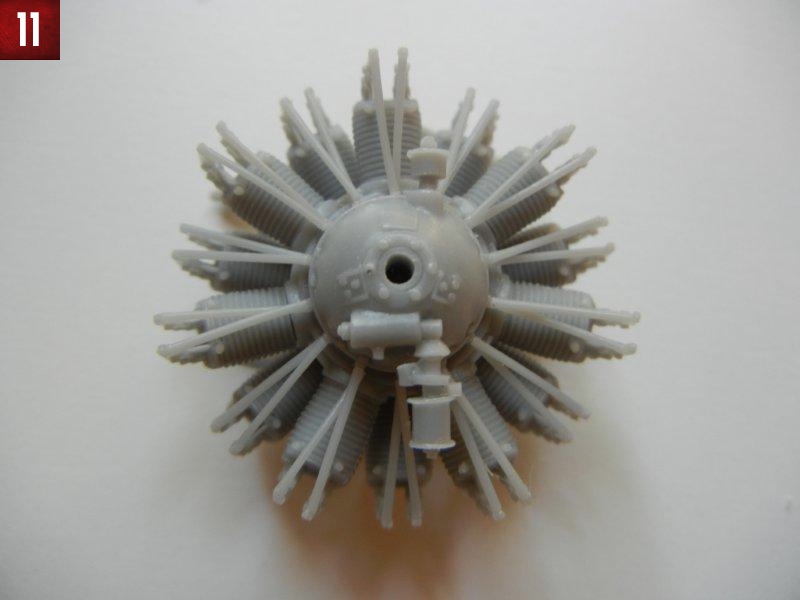
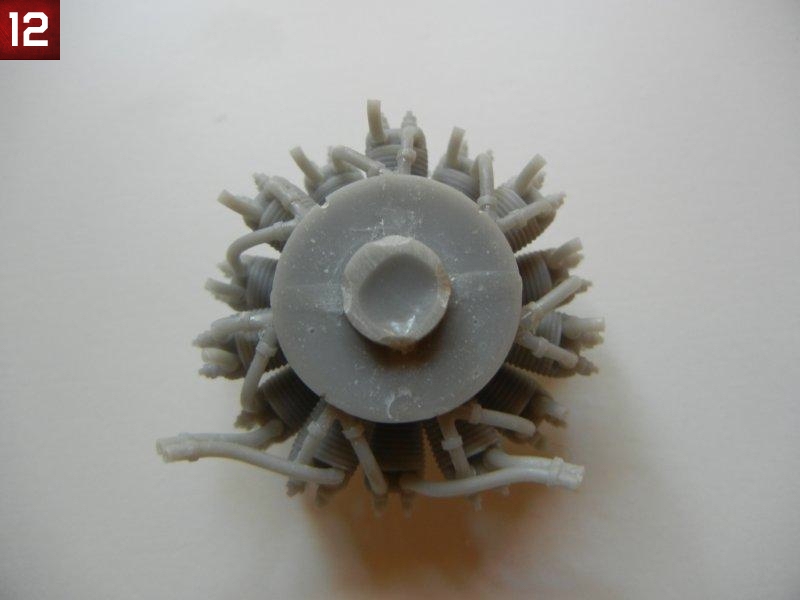
- Photos 11 and 12 show the completed engine.
Lower wings
The ailerons and "butt joined" to the lower wings. I left them this way for this build guide to see how they would hold up. I am happy to report they have remained in place without issue with lots of handing (not just by me). However, I would recommend that you mark and drill out holes in the mating surfaces for two or three brass/wire rods. This will give you both the advantage of a stronger join, and the ability to easily deflect the ailerons if desired.
- Begin by drilling out the strut (and rigging if desired) attachment holes in the lower wings as indicated. See the article "Making Templates" in the "Tips and Reviews" section of the Silver Wings website (www.silverwings.pl) for tips on drilling out these holes at the correct angle.
- Attach the ailerons into position. Once dry, attach the PE plates (PE12) as indicated (see photo 13).
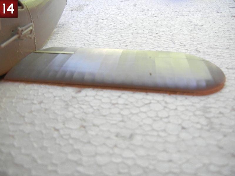
- When set, attach the wings to the completed fuselage assembly. As the lower wings should have 0 dihedral, you can use a flat surface to help keep them level (see photo 14).
- I recommend waiting to install the control cable guides to the bottom of the wing until final assembly.
Upper wings and wing attachment
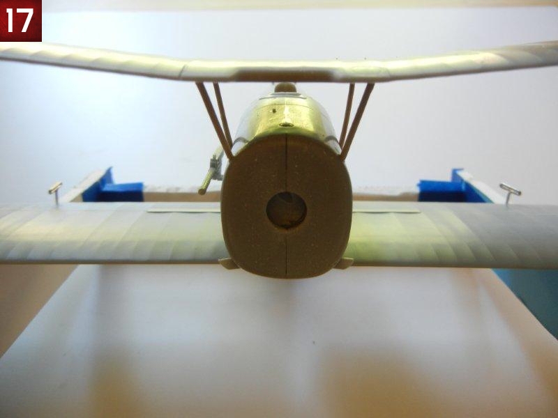
Note that I assembled my kit using the 13mm dihedral indicated in the instructions, and only after the wing was set, did I note that there appeared to be too much dihedral in the top wing and followed up with Silver Wings to determine the correct measurement (11mm).
Like the lower wings, the ailerons are "butt joined" to the upper wings. If you used the brass/wire rod option suggested above, you should also do so for these wings.
- Again, begin by drilling out the holes for the struts (and rigging if desired) in the fuselage, center and outer upper wings.
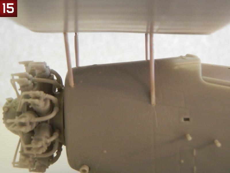
- Dry fit the cabane (wing to fuselage) struts to the fuselage, and then test fit the upper wing center section (photo 15). On my example, I found the rear cabane struts (the longer set) to be a little long, and I had to press them down into the fuselage holes to get the proper wing position. However, as the correct 11mm dihedral will raise the center wing section, you may actually find the forward cabane struts to be a tad short. Accordingly, I recommend not trimming the cabane strut wire cores at all until you have been able to dry fit the completed wing with the interplane (wing to wing) struts to determine the needed cabane strut length. Any shortness can be overcome by trimming the wire cores appropriately.
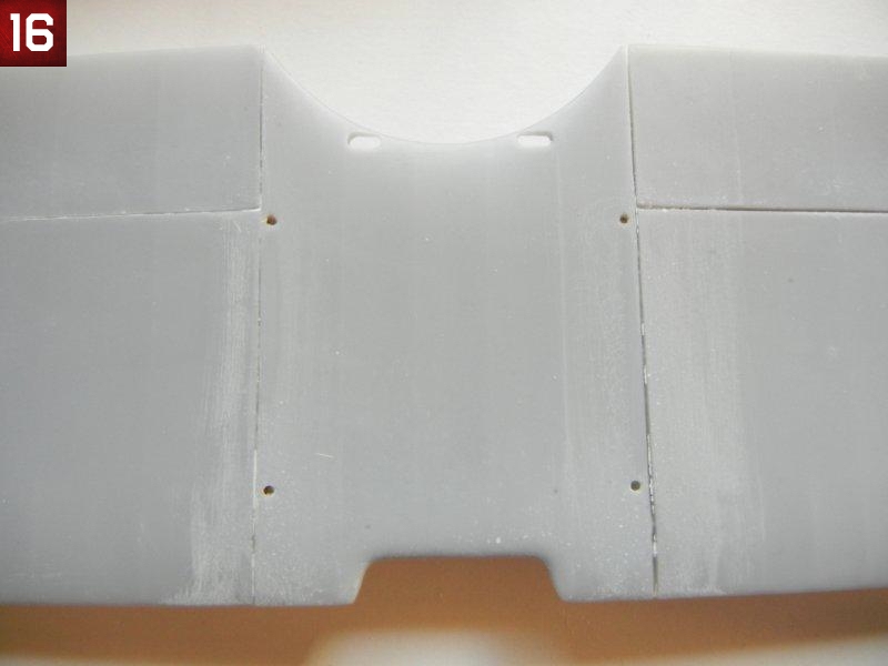
- Attach the outer upper wings to the wing center section, setting the dihedral at 11mm at the outer tip. Again, see the article "Making Templates" in the "Tips and Reviews" section of the Silver Wings website (www.silverwings.pl) for tips setting the correct dihedral. When dry, my wings had slight gaps on the underside, which were filled by the superglue used to join them (see photo 16).
- You may want to use a jig for the remaining steps. See the article "Easy Biplane Jig" in the "Tips and Reviews" section of the Silver Wings website (www.silverwings.pl) to create a simple jig for aligning your wings.
- Once set fit the interplane struts in place, and then test fit the upper wing in position using the interplane struts only. On my example, the center interplane strut was slightly short, but fit fine as I left the wire core long enough to make up for the missing length. However, as with the cabane struts, you may find that the center interplane strut is the correct length and the forward and rear interplane struts are long when fitting a wing with the correct 11mm dihedral.
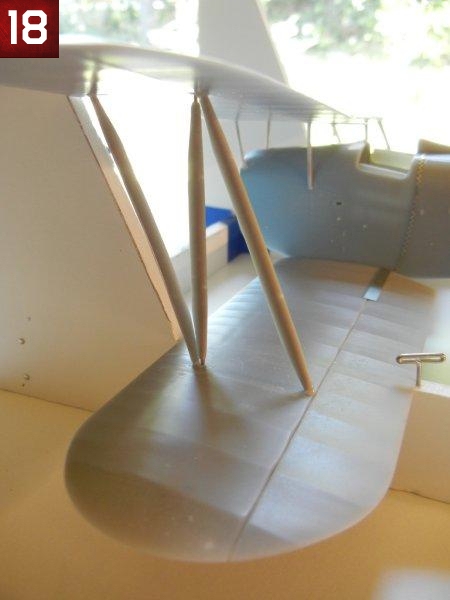
- Remove the upper wing, dry fit the cabane struts and interplane struts and upper wing (photos 17 and 18). Trim the wire cores as needed to get the correct strut lengths .
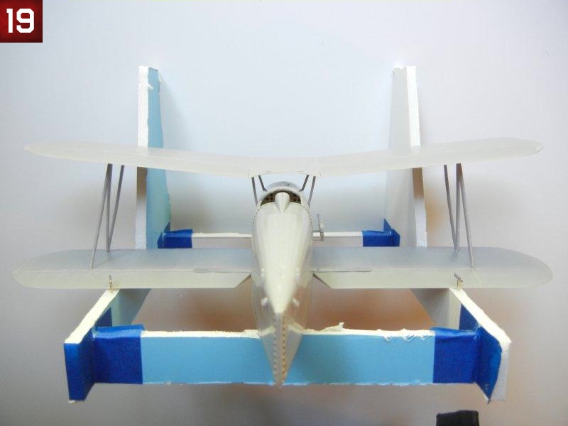
- Once satisfied with the fit, glue the struts and upper wing in place (see photo 19) using a jig if desired.
- I recommend waiting to install the control cable guides to the bottom of the wing until final assembly.
Rear Empennage
The rear empennage is covered by steps 24 and 26.
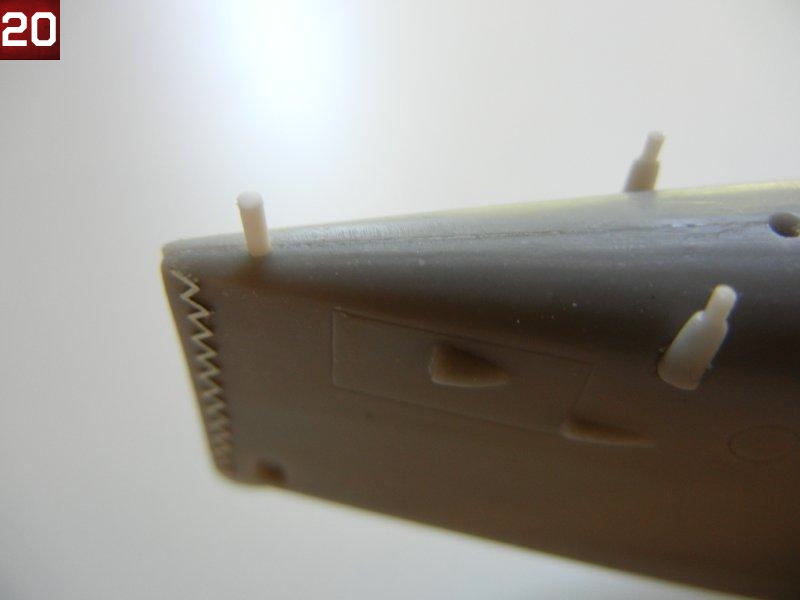
- I began by marking the position of the rear support rod and drilling a hole in the fuselage in the appropriate position (see photo 20). This allowed me to use a longer piece of styrene rod, and I could then adjust the rear height as needed to ensure optimum fit.
- I glued the rod into position on the tailplane (and enlarged the fuselage hole fore and aft for easier fitting (photo 21). I then test fitting the tailplane to the fuselage support rods, which showed that the pre-marked holes in the bottom of the tailplane were in the wrong position. Mark the correct position by placing a small drop of paint on each of the forward support rods, and then placing the tailplane in the correct position. Drill the holes in the appropriate place, which were outboard from the pre-marked holes for my example.
- Drill out the support brace holes in the bottom of the tailplane and test fit the tailplane to the fuselage. Using the support brace, determine the appropriate forward fuselage attachment position, and mark and drill the attachment hole (there is no pre-sunk hole for this part) see photo 22.
- Test fit the rudder/vertical stabilizer to the fuselage. I needed to sand the lower portion of the rudder to get a good fit (see photo 23).
- Attach the control horns to the bottom of the tailplane and attach the tailplane and support struts into position (see photo 24).
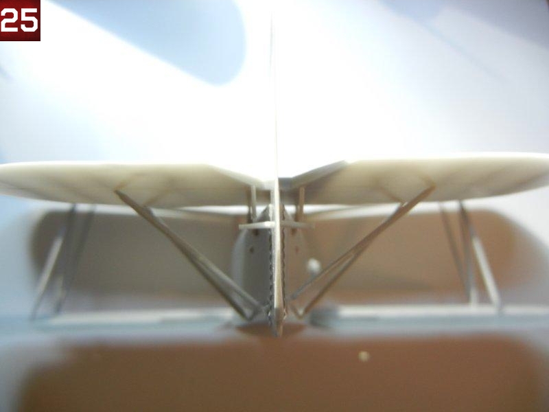
- Attach the control horns to the rudder/vertical stabilizer into glue into position. Photo 25 shows the completed rear empennage.
Main Gear
The main gear appears complex, but it is fairly easy to attach correctly. The assembly consists of a main axle and upper support axle (main axle assembly), a main strut (the fat one with the shock absorber) and a rear (longer) and forward (shorter) support strut.
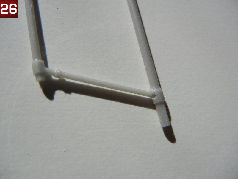
- Begin by drilling holes for the main struts into the main axle (photo 26). You can use the drawing on page 6 to make templates to align your holes correctly. You will need to drill two holes for the forward and rear support struts on each side of the upper support axle for the support struts.
- Drill the corresponding strut attachment holes in the fuselage bottom for the main, forward and rear support struts, again using a template using the pre-sunk holes.
- Dry fit the main strut to the main axle, trimming the wire core so that it is not visible outside the attachment hole. Dry fit the main axel assembly to the main, rear and forward struts (you might need 3+ hands for this step - so tape is your friend). Check your alignment and adjust as required.
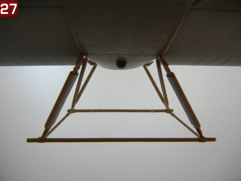
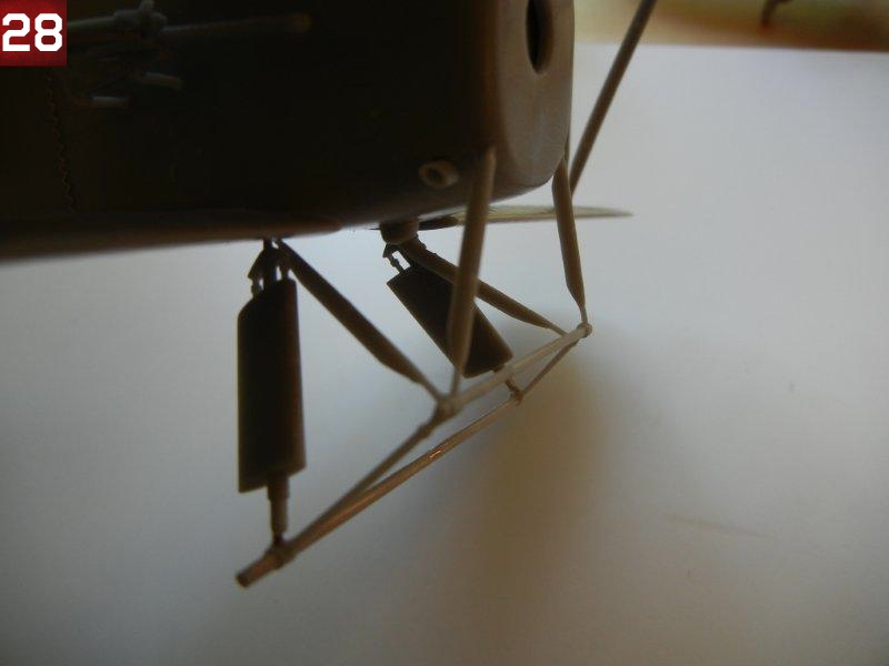
- Once satisfied, glue the main strut, rear and forward struts to the fuselage. Then attach the main axle assembly to the main, rear and forward struts. Re-check alignment. Photos 27 and 28 show the completed assembly (note the port side rear support strut has become detached from the support axle in the photos - oops!)
- Glue the main wheels to the axles. Unlike other Silver Wings kits, I did note that the holes in the main wheels were a bit larger than the axle itself, so you'll need to hold them in the correct position until your glue sets.
Final Assembly
- Steps 28 and 29 provide the rigging and control cable installation guides.
- Attach the engine (and long exhausts if your model uses them).
- Attach the guns sight to the fuselage. Cut out and test fit the acetate windscreen bending as needed to fit the molded in framing on the fuselage.
- Attach the guns or gun brackets into position.
- Attach the tail skid to the bottom of the rear fuselage using the hole provided (I had to enlarge mine slightly for a good fit).
- Attach the control cable support guides into position on the ailerons of the top and bottom wings. If you are going to attach the control cables, Silver Wings has molded pre-sunk holes for the cables in the wings and ailerons.
- Finally, attach the pitot to the forward starboard interplane strut and PE rope holders to the top of the center wing.
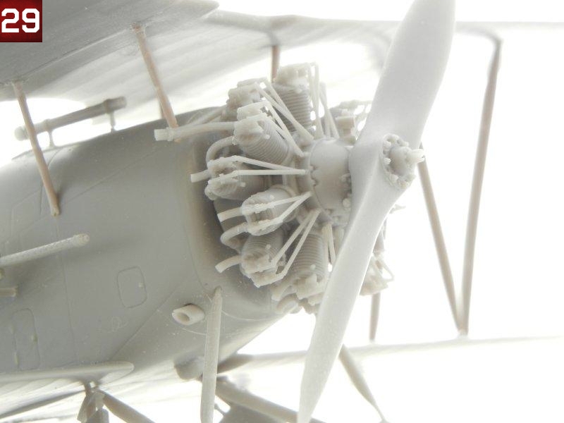
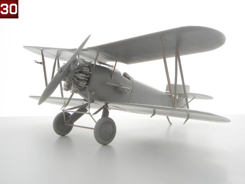
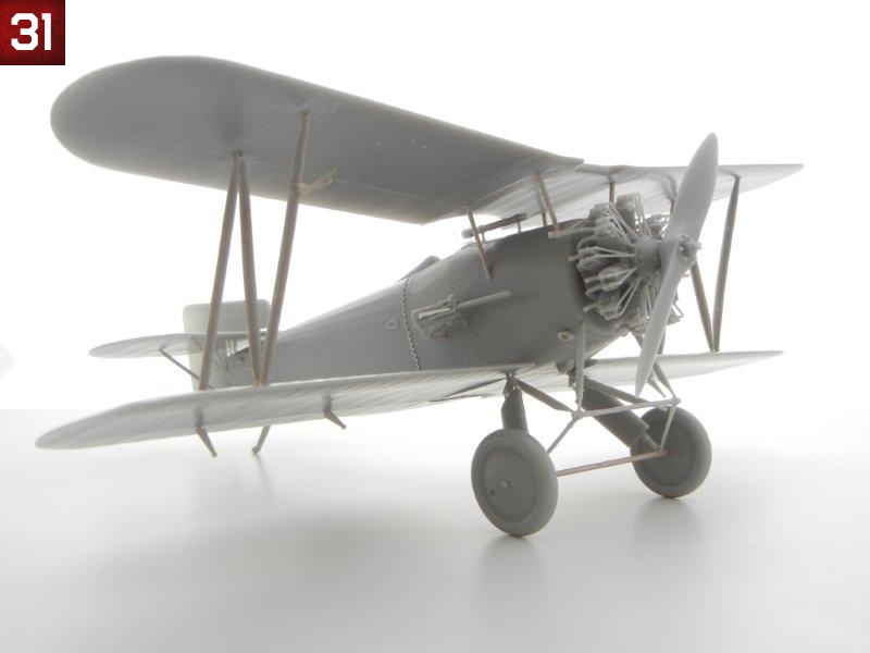
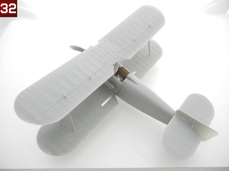
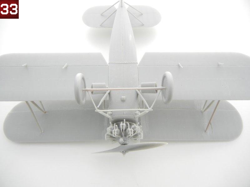
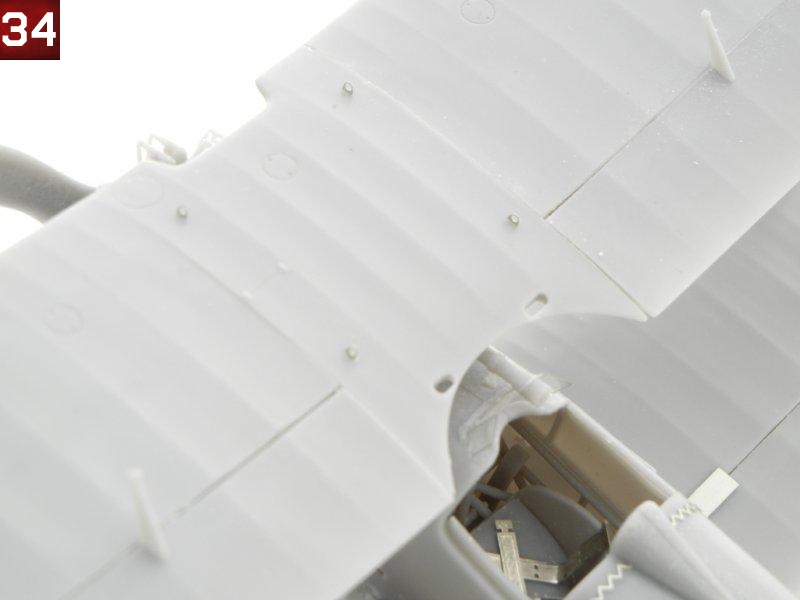
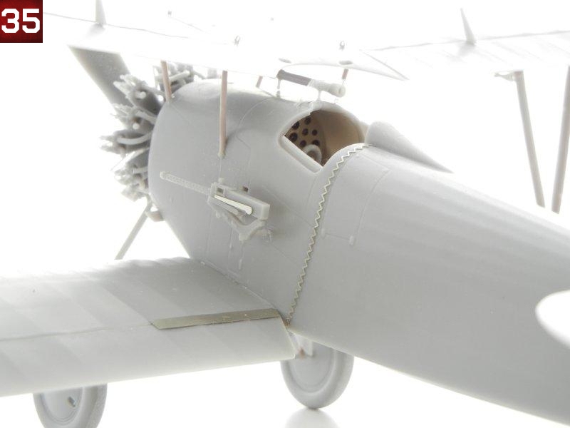
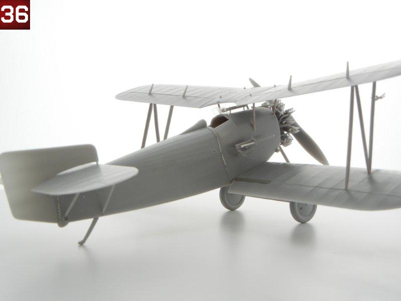
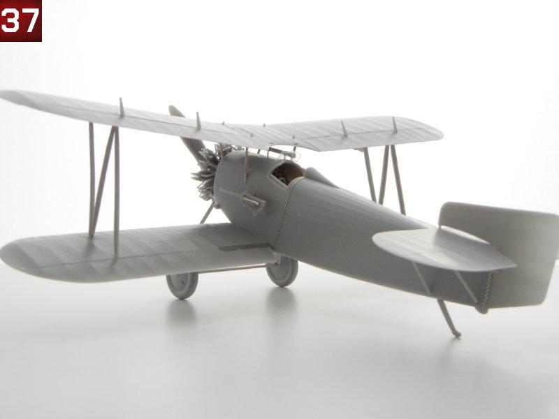
Congratulations on your newly finished model! Photos 29 ~ 38 are of the completed model.
Photos and text copyright Doug Nelson (2012)
Gallery