1:32 Boeing Stearman PT-13D/N2S-2
 |
 |
 |
Silver Wings 1/32 Boeing Stearman PT-13D/N2S-2 build guide
General
This kit gives the builder the option to do either a Navy N2S-2 or an Army Air Corps PT-13D version. Be sure to review the instructions and highlight which parts you will need for the version you are building. Also note that I used standard superglue for all assembling, with the exception of the struts, where I used slower setting superglue gel to give me more time for adjustments.
Parts Cleanup
As with other Silver Wings kits, parts cleanup is fairly simple, and due to the soft resin they use for their kit, a sprue cutter can even be used to snip most parts from their pour stubs without damaging the part. After that, a few scrapes with the Xacto knife and/or sanding stick and the part is ready for use.
With these kits, since there are no part numbers to worry about, I like to clean up all the parts and then begin the build. Any parts can be painted as appropriate after cleanup and before assembly as well. A few things to note when preparing your kit parts for use:
- The upper and lower wings have excess resin “rods” on the upper tips, these must be removed as the outer wing should be smooth.
- Check your fuselage framing for any breaks before you remove the pour blocks. You should repair any breaks with superglue before removing the pour blocks.
- If you intend to use the kit provided cockpit frame cross brace tubes, be sure to measure them before you remove them from the pour stubs as I found I had to trim carefully in order to not end up with tubes that were too short.
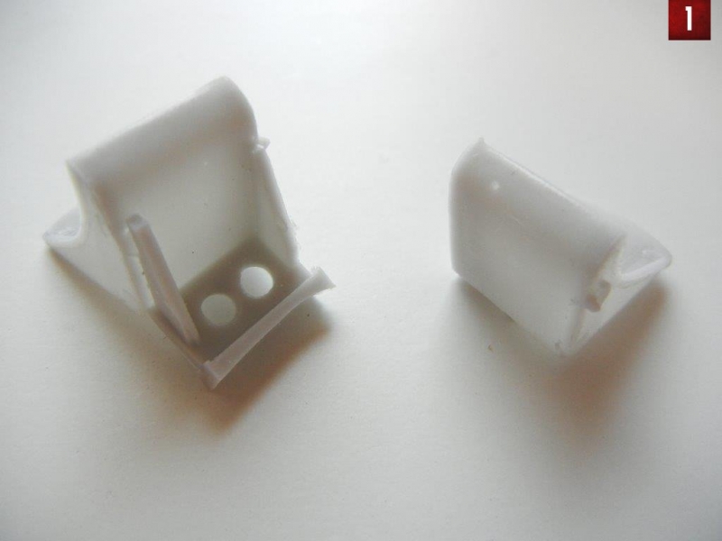
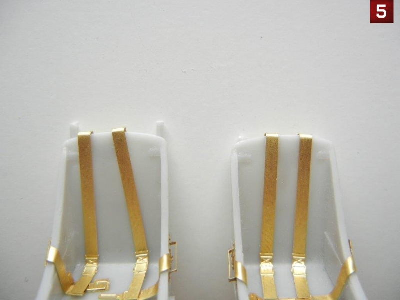
- Although it make look like framing/support, be sure to remove all the pour block from the bottom of the seats. Photo 1 shows one with the pour block and the other with this removed.
Interior Subassemblies
There are a few items that can be assembled before installation in the cockpit, as indicated on page 2 and 4 of the instructions. I'll review them here:
- Rudder pedals (4 of them): Each rudder pedal consist of 2 resin parts and a PE part. I found that I needed to enlarge the hole on the PE part to get it to fit properly over the rudder bar.
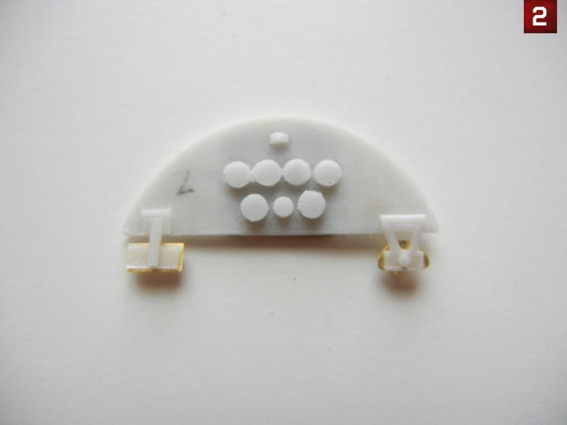
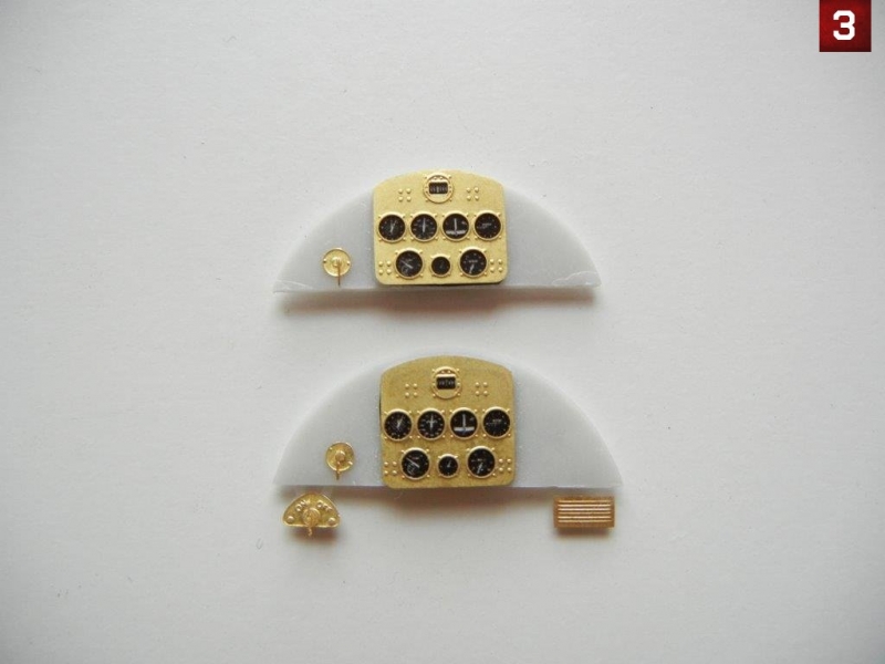
- Instrument Panels: Each instrument panel is created using a resin base panel, acetate instrument film and PE parts. I found the instructions to be incorrect when it comes to which of the main instrument PE/acetate parts went to each panel. They are reversed on the instructions and the "control panel - 1st pilot" panel should have PE part 13a (instead of part 13b) and acetate "film 1" (instead of "film 2"). "control panel - 2nd pilot" should therefore have PE part 13b and "film" part 2. Photo 2 shows the back on the "2nd pilot" panel, which hopefully will help the builder indentify the correct brackets to attach PE parts 3 and 7 to. Photo 3 shows the completed panels.
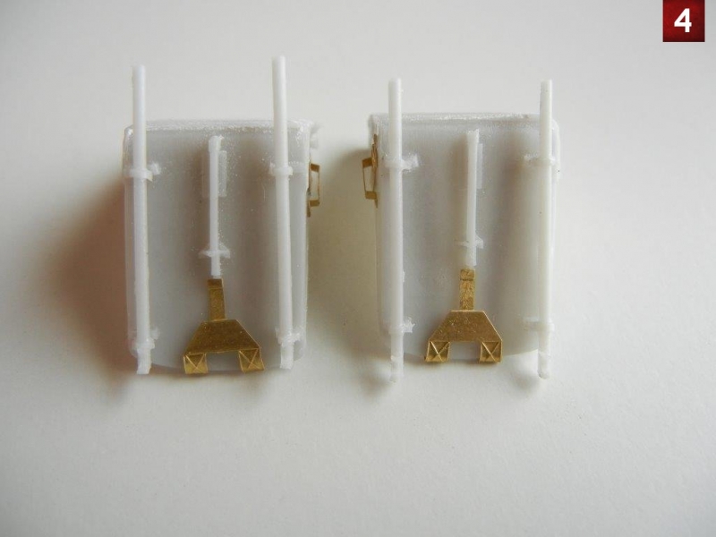
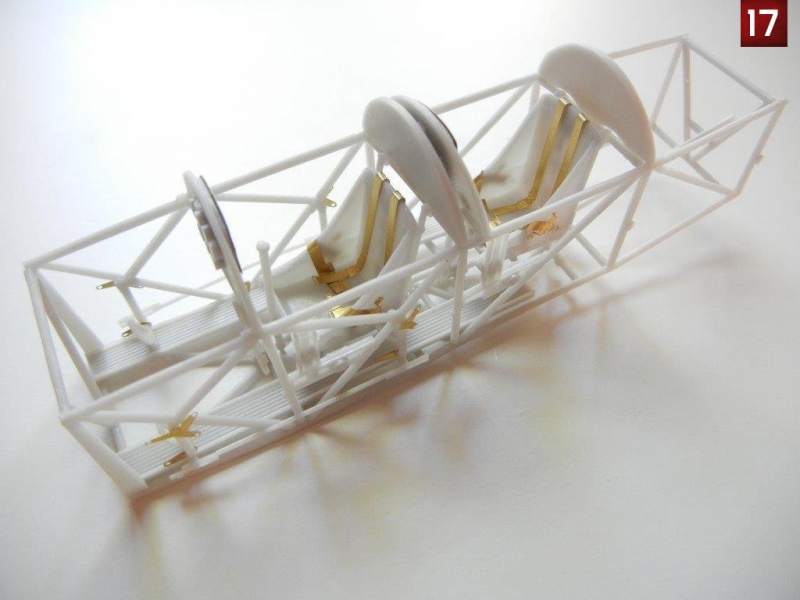
- Seats: Each of the two seats has some frames that attach to the back. There are two different styles of frames, so be sure attach one matching set to each seat. One set will attach so that the top of the frame is level with the top of the seat, while on the other, the top of the frame will extend above the top of the seat Photos 4 and 5 shows the assembled seats for reference. Before attaching the seatbelts, bend and attach the handle on each side of the seat (PE#12) as the lap belts pass through this handle.
Cockpit Assembly
Cockpit assembly is shown on pages 5 and 6 of the instructions. If you've built any other Silver Wings kits, assembly should be familiar to you. Interestingly, I found this to be the easiest cockpit to build compared to other Silver Wings kits.
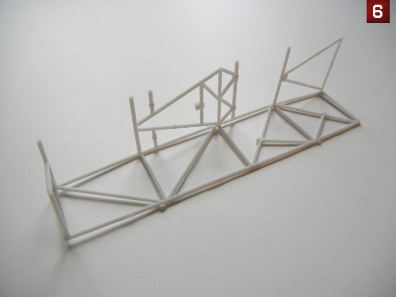
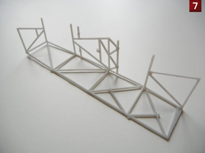
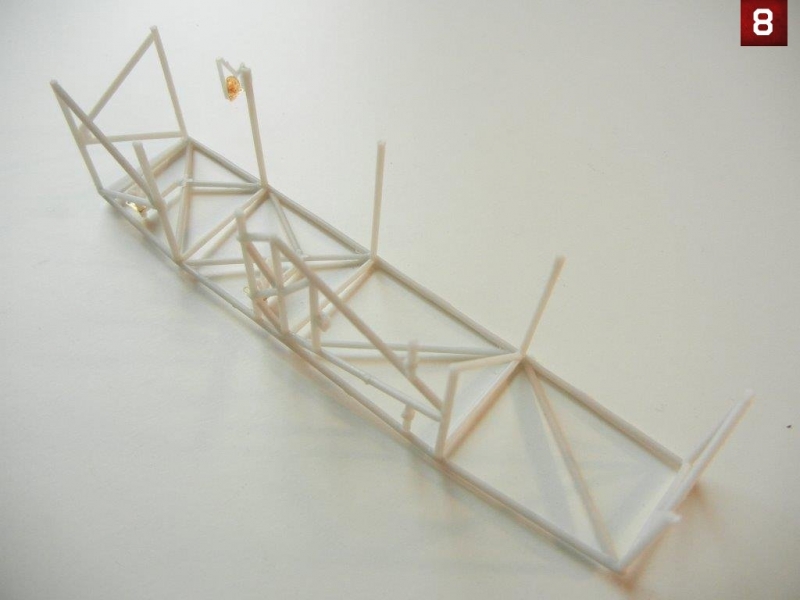
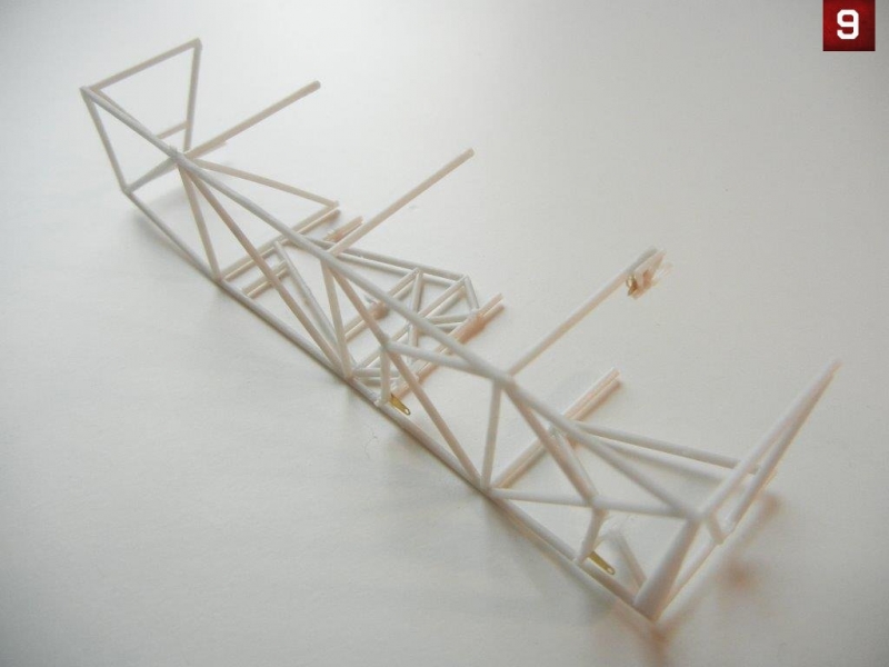
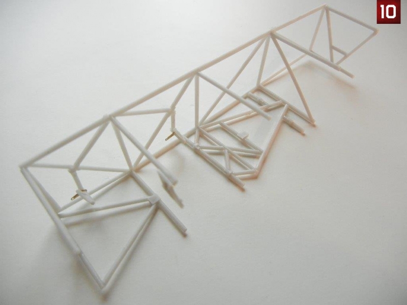
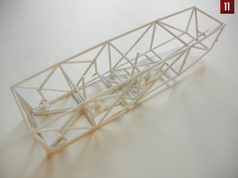
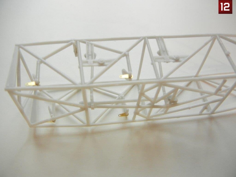
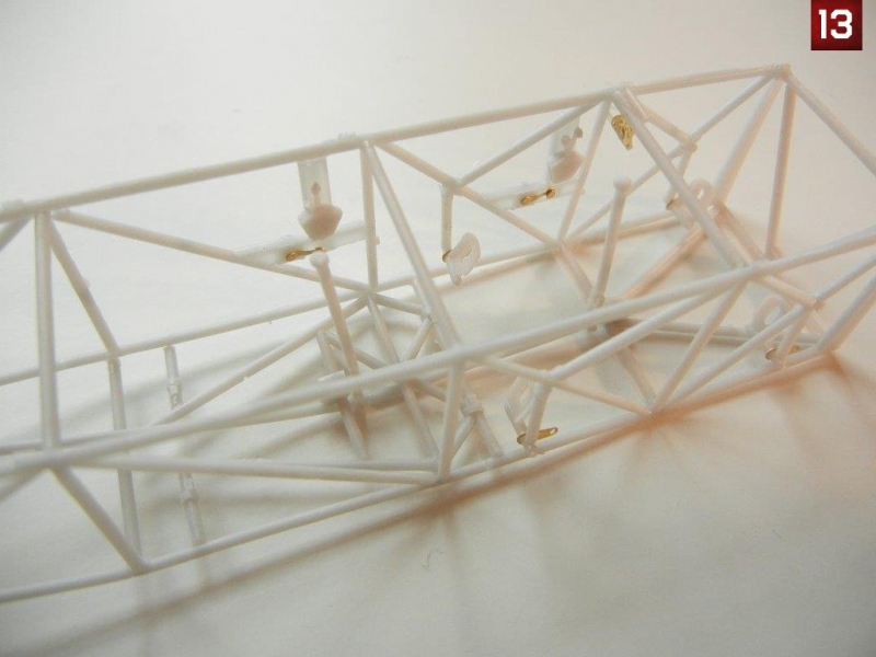
- I started my assembly by attaching the center framing sections to one side of the cockpit frame (photos 6 & 7). I then cut the provided resin cross-braces to the appropriate lengths as indicated on page 5. I took one of the 23mm cross frames and added the support and PE as indicated in the "A" subsection on page 5. I then added the rudder pedal assemblies to the appropriate spots as indicated on page 5, and then attached the upper cross frames (see Photo 8-10). I then attached the diagonal cross frames, and added the control linkage (Photo 11 & 12). Finally, I added the side control panels from page 2 (photo 13). Once complete, test fit the frame into the fuselage to be sure everything is lined up properly.
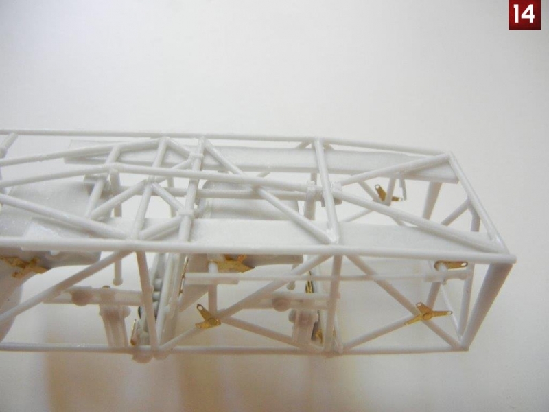
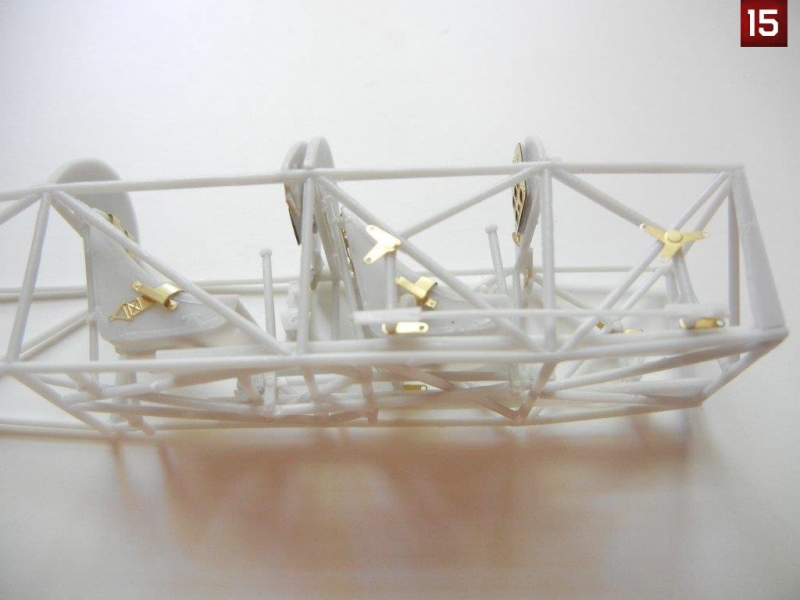
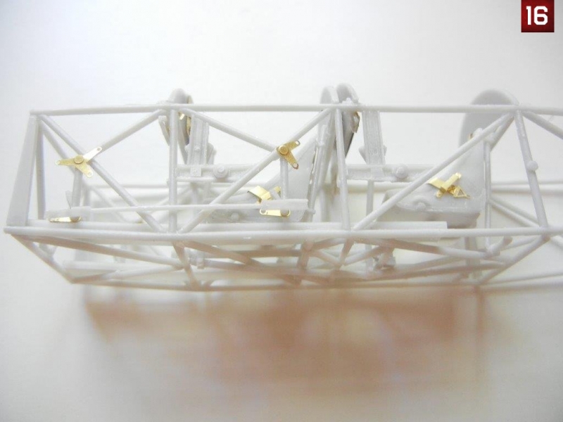
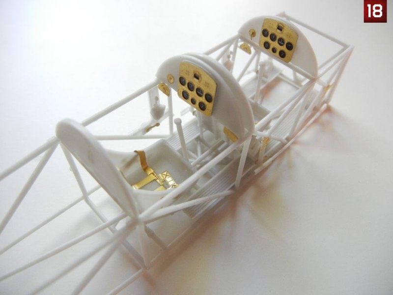
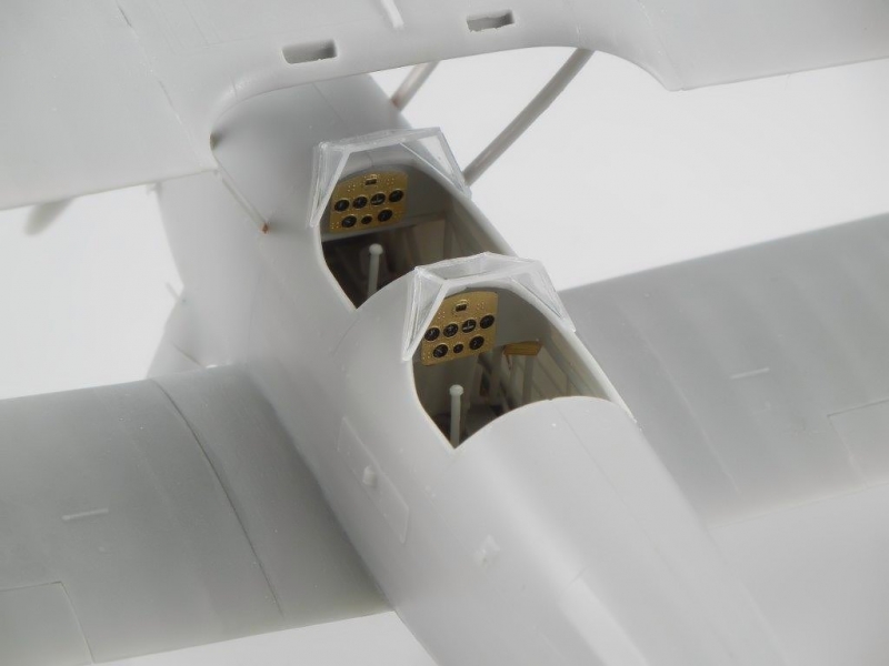
- Next, slid the foot troughs into position and glued them in place. I then added the two seats, being sure to put the "lower" seat with the framing extending above the back of the seat in front, with the other in the rear position (photo 14). I then added the IP panels, being sure to place the one with the PE parts on the bottom in the rear position as indicated on page 6 of the instructions. I also placed two "bulkheads" that are shaped like the IP and sit on top of the cockpit framing. Be sure to put the one with the "I" behind the front seat and the one with the "II" on it behind the rear seat. Finally, I added the rudder linkages and remaining PE on each side as shown on page 6. Photos 15-18 show the completed cockpit assembly.
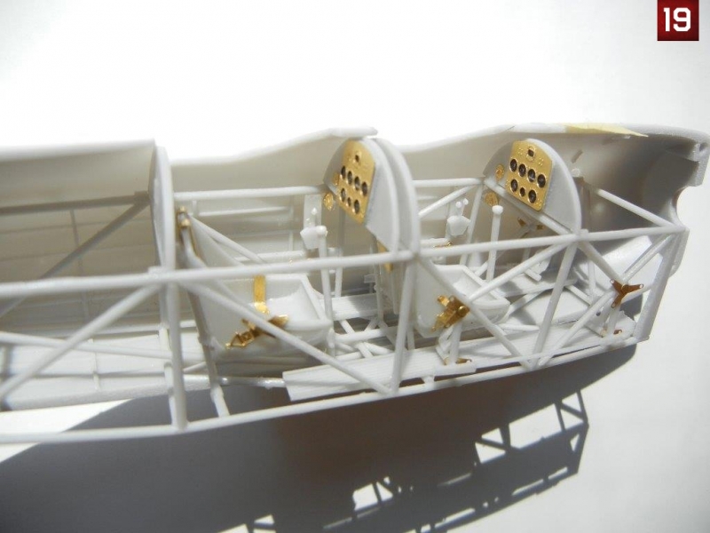
- Add the control wires as shown on page 7 of the instructions if desired. Finally, test fit your completed cockpit in the fuselage (Photo19).
Fuselage Assembly
Fuselage assembly is covered on page 8/9 of the instructions.
- Prior to assembling the fuselage, I drilled out an additional hole on each side of the wing root to allow the metal rod on the lower wing to fit into the fuselage. You can make the hole a bit larger than the rod to ease optimal fitting of the lower wing.
- Attach the fire extinguisher to the port side fuselage half as indicated on page 8.
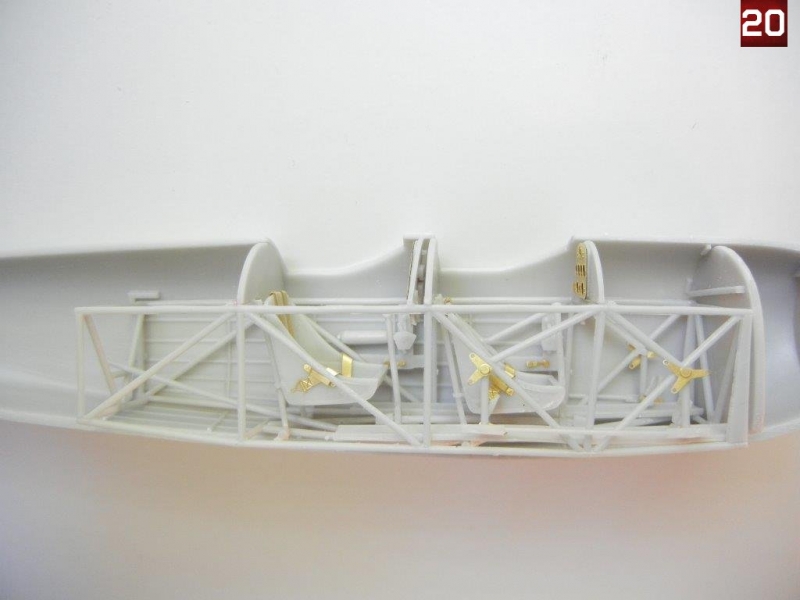
- Although the forward bulkhead magically appears on the assembled cockpit in the illustration on page 9, I chose to attach it to the port side fuselage half instead. I then installed the completed cockpit frame to one of the fuselage halves. Photos 20 shows the cockpit in place and everything ready to be closed up.
- Glue the fuselage halves together.
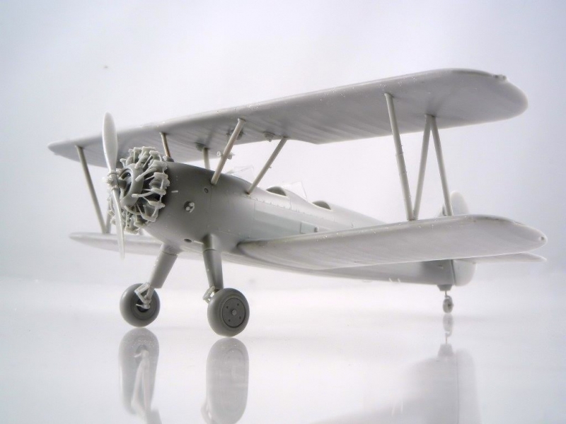
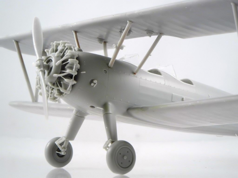
Engine Assembly
Engine assembly is covered in the upper section of page 3 of the instructions, although you can complete this step at any time during the assembly of your model. This engine is different that previous Silver Wings engines in that it has tubes that bridge the top of each cylinder head, as well as connect between them. While the kit provides these parts as resin pieces, it may be easier to simply replace them with some wire, as the provided resin parts do not have significant excess to allow for proper fitting in the event your cylinder heads are slightly mis-alinged.
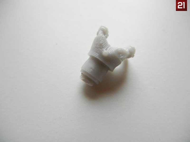
- When cleaning up the individual cylinder heads, be sure to leave enough of the lower section to fit into the holes in the engine crankcase (Photo 21). If you plan to use wire for the bridge and connecting wires as recommended, you should drill holes to accept these wires in the cylinder heads prior to assembly. Please consult your references for proper placement of the wires and drill the corresponding holes.
- Attach the cylinder heads to the crankcase as shown in the instructions, taking care to ensure they are properly aligned.
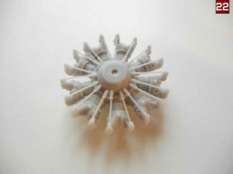
- Cut the pushrods (one or two at a time if you are prone to losing things like me) from their pour blocks and test fit it to the engine block/cylinder head. If the length is good, you can glue into place. Repeat the process until all 18 pushrods are in place (Photo 22), I would recommend the use of unpainted steel wire or rod rather than the kit parts for a more striking look.
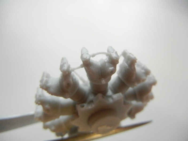
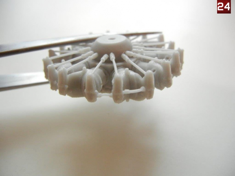
- Add the bridge (long) and connector (short) tubes to the cylinder heads, or add wire if you chose that option. Photos 23 and 24 show these tubes in place.
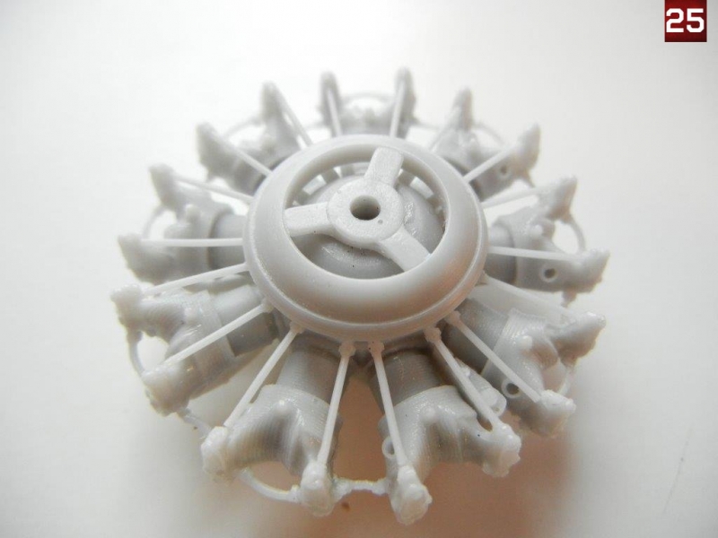
- Assemble the exhaust collector ring, and attach it to the front of the engine (Photo 25)
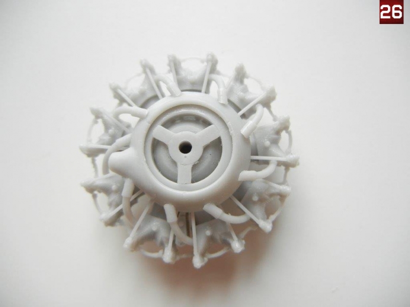
- Add the 9 exhaust pipes to the cylinder heads and exhaust collector rings (Photo 26)
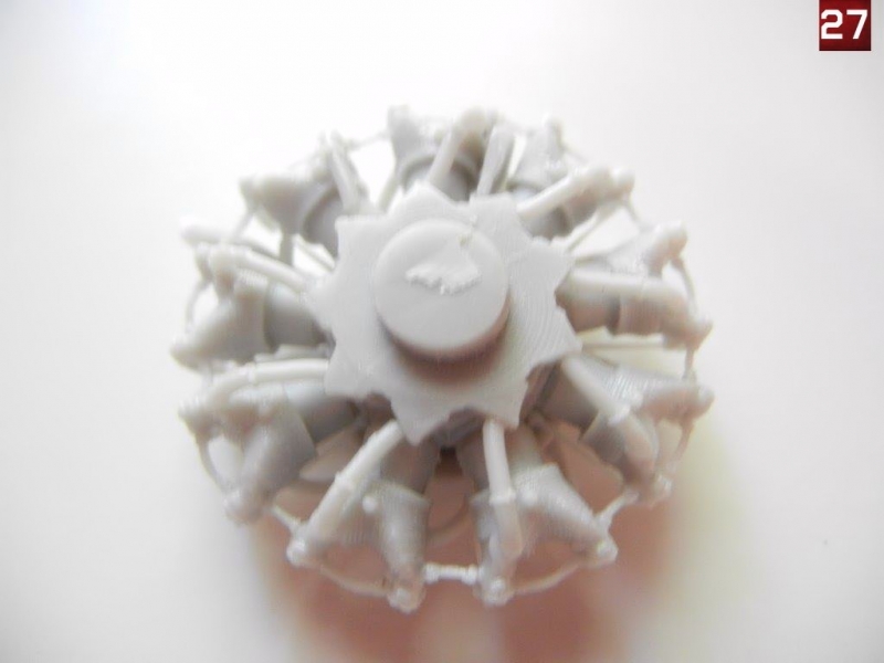
- Finally add the 9 intake pipes to the cylinder heads/crankcase (Photo 27).
Lower wings
The lower wings have a metal rod inserted for strength, the remains of which can be used for attaching the lower wings to the fuselage. As mentioned in the fuselage section, I recommend drilling out the appropriate hole on each side of the fuselage attachment point to accept the entire metal rod.
- Begin by drilling out the strut attachment holes in the lower wings as indicated by the small indents. You can drill these at the correct angle for the metal rod that sticks out of each end of the strut by simply transferring the angle from the plans onto a piece of cardboard or paper (see the "Tips and Hints" section of the Silver Wings website for more information if needed). Note that the angle of the holes does not have to be perfect, as the brass rod in the struts will allow you to bend them a little to adjust their fit a little if needed.
- If you will be rigging your model, you may also want to drill the appropriate rigging holes in the lower wing at this time. Page 14 of the instructions provides a rigging guide.
- Attach the ailerons to the wings as indicated on page 8 of the instructions. You can drill holes in the wing attachment surface, and ailerons and use some brass wire to pin them for additional strength.
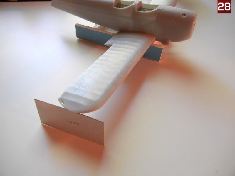
- Attach the wings to the completed fuselage assembly. Note the lower wings should have 7mm of dihedral at the tip according to page 10 of the instructions. Because the fuselage extends below the level of the wings, I built a small cradle of foamcore 20mm high, and then made a cardboard spacer of 27mm (20mm cradle + 7mm dihedral) to ensure the proper angle (see photo 28).
Upper wings and wing attachment
The good news is that this kit has had the easiest upper wing attachment of virtually any other biplane kit I have built, and attaching it is very straightforward. The upper wings should have 5mm of dihedral according to the instructions (page 10). Although not shown in the instructions, you will need to join both upper wing halves to the center piece. As with the lower wings, I recommend you drill out the appropriate holes for the struts. I would also recommend leaving off the items attached to the bottom of the wing center section (shown on page 8) until after the wing has been assembled and test fit.
- Test fit the upper wings to the center section and check the dihedral, adjust as necessary. When satisfied, glue together. I used the same foamcore cradle that I made for attaching the lower wings as a base for the center of the wing since there is a protrusion that does not allow the wing center to remain flat. I then simply added the 20mm to the 5mm dihedral and used a 25mm spacer taped to the bottom of the wing tip (photo 29).
- Drill out the strut attachment holes in the upper wings as indicated by the small indents. As with the lower wing, note that the angle of the holes does not have to be perfect, as the brass rod in the struts will allow you to bend them a little to adjust their fit a little if needed.
- If you will be rigging your model, you may also want to drill the appropriate rigging holes in the upper wing and fuselage at this time. Page 14 of the instructions provides a rigging guide.
- I started by attaching the cabane (center) struts to the fuselage using the holes I drilled as shown on page 12 of the instructions. I then used the upper wing to check their alignment before the glue set. (Photo 30). You may also make a template using cardboard or plastic by drilling holes in it to match the holes in the bottom of the upper wing (see CR.42 Build Guide for details) if preferred. Due to the wire core used by Silver Wings, just these 4 thin struts were enough to hold the entire wing in place.
- I then attached the interplane (outer) struts to the lower wing, again using the upper wing as a guide before the glue set.
- Once the test fitting was complete, I attached the items to the bottom of the wing center section as shown on page 8 of the instructions.
- I then attached the front windscreen just to be safe, although fitting it after the wing is attached should not be a problem as there is plenty of clearance.
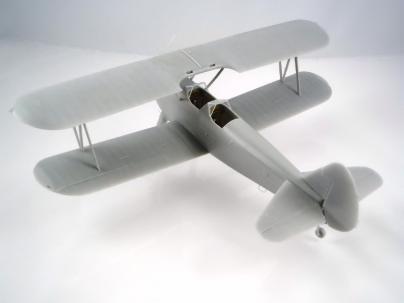
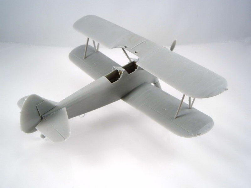
- Since the fit of the wing was so good, I simply attached the upper wing, and secured the model to my foamcore jig to ensure proper alignment of the upper wing (Photo 31).
Rear Empennage
The rear empennage is covered on page 11. Note that you can install these parts at any time after the fuselage is completed.
- I began by attaching the vertical stabilizer to the fuselage, and then attached the tail planes to the fuselage.
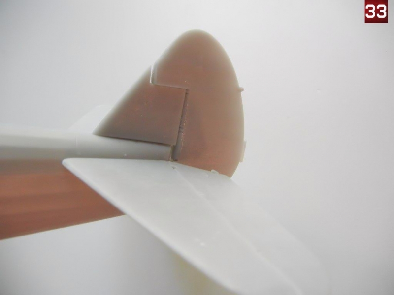
- When attaching the rudder, the orientation/location of the two control horns (one on either side) is unclear. After consulting reference photos, I was able to attach them in position. Photo 32 shows the installed control horn orientation/position.
- Photo 33 shows the completed assembly. You can paint the tail lamp molded on the rudder, or I would recommend replacing it with a a piece of clear sprue.
Main Landing Gear
The main gear struts are shown being assembled on page 2 of the instructions, and shown being attached on page 12
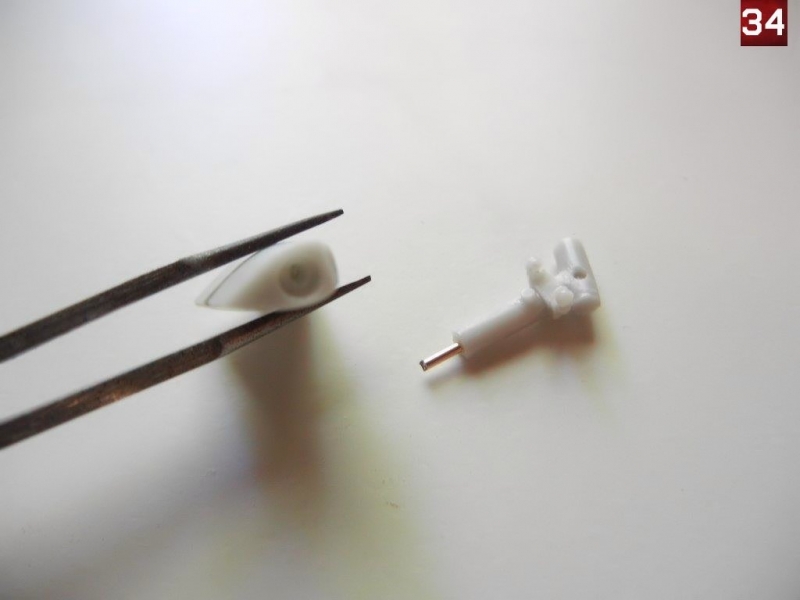
- As the axel part has a wire core imbedded in it, I drilled out the main gear leg to accept the protruding wire for extra strength (Photo 34)
- I then attached the two scissor links to the gear leg. The upper part has the larger attachment point, while the lower part has the smaller attachment point.
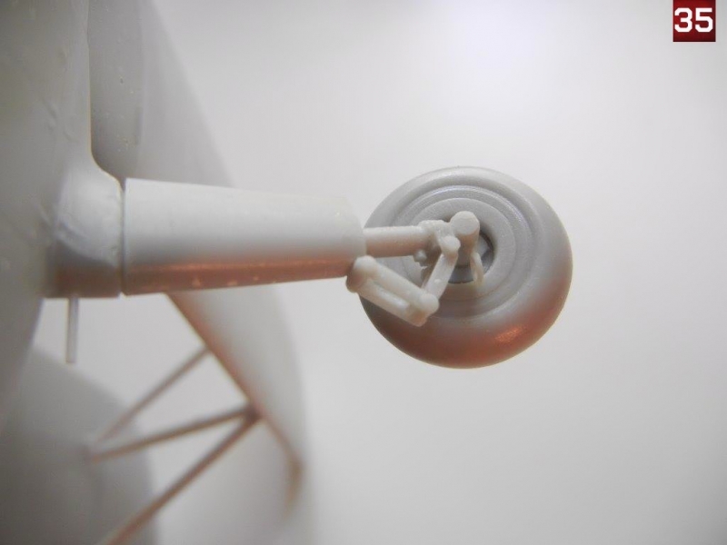
- I then attached the gear legs to the fuselage. Note that fit should not be perfect based on photos of the actual aircraft. Once dry, I added the wheels to each gear leg. Finally, I added the tow ring to the front of each gear leg.
- Photo 35 shows the completed gear assembly.
Final Assembly
- Attach the engine to the fuselage, taking care to ensure it is aligned properly. The fit on my kit was tight enough that I did not need to glue it in place.
- If you are building the N2S-2 version, attach the wooden prop. I found that the "pin" for attaching the prop was smaller than the hole it goes into, so I would recommend removing the pin, drilling a hole in the back of the prop hub and inserting an appropriate sized plastic or metal rod and using it to attach the prop.
- If you are building the PT-13D version, assemble the metal prop as shown on page 4 of the instructions. I had to drill out the holes and shorten the attachment points on the prop blades to get them to fit properly into the prop hub.
- Add the venturi tube to the appropriate cabane strut. If you are adding the fuel lines as shown on page 10 of the instructions you can add them before the wing is attached if you prefer. Also add the pitot tube to the appropriate interplane strut as shown on page 12 of the instructions.
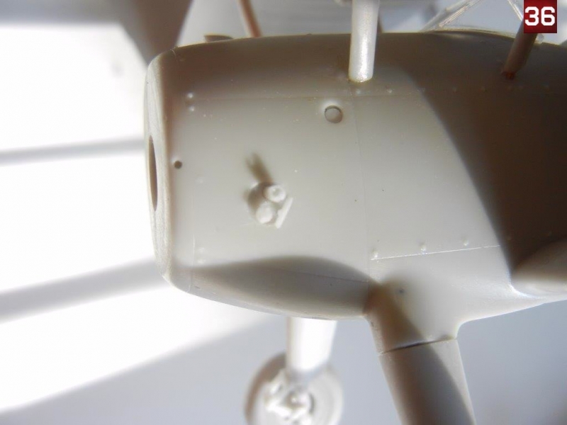
- Add the small parts to the round indented area on the port fuselage front as shown on page 10 of the instructions. Photo 36 shows these parts in position for reference. However, when looking at photos of the real aircraft it seems there are multiple combinations for what parts go in that space, so check your references for the aircraft you are building.
- Attach the windscreen(s) and the intake pipe (shown on page 10) to the fuselage.
- Attach the 4 small "tubes" to the front of the fuselage/gear struts as shown on page 12 of the instructions. You can use the kit provided resin rods, or replace them with metal rods if you prefer
- Attach the two grab handles on either side of the lower fuselage as shown on page 12 of the instructions.
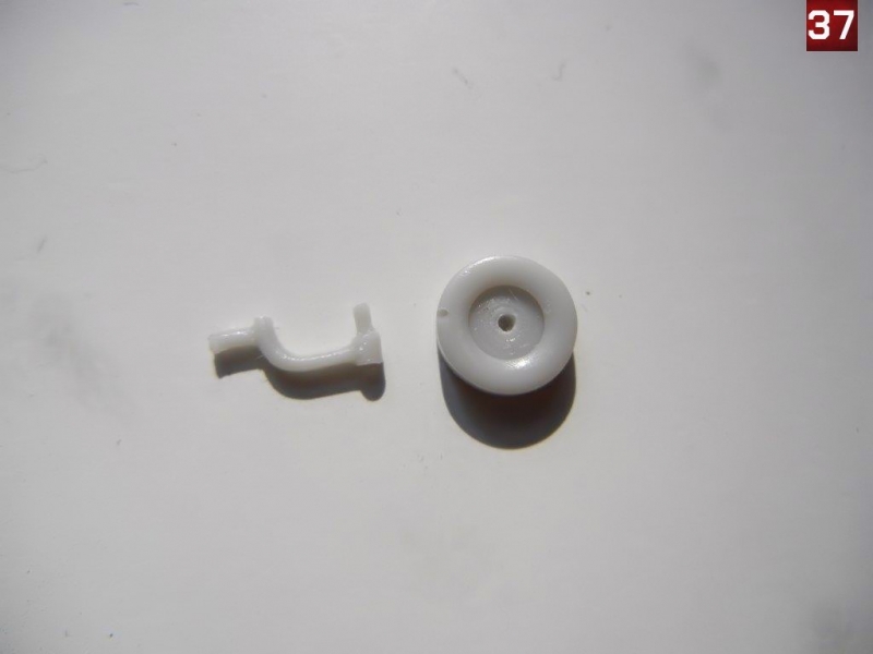
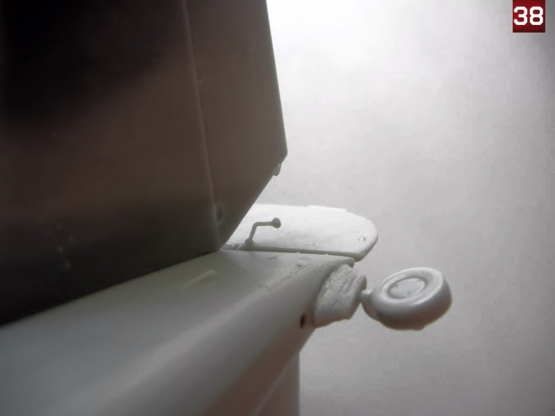
- The tail wheel strut is quite fragile, so I recommend leaving it until last. You can attach the "boot" at any time however, noting that the "pointy" end faces towards the front. You will need to drill out a small attachment hole in the tail wheel (Photo 37) in order to attach it to the tail wheel strut. If your tail wheel strut breaks (as mine did during lots of handling for photographs for this Build Guide) you can replace the main rod with some brass wire. Page 2 of the instructions shows the assembly of the tail wheel. Photo 38 shows the completed tail wheel assembly.
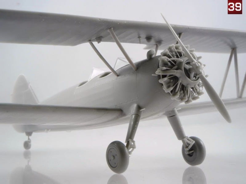
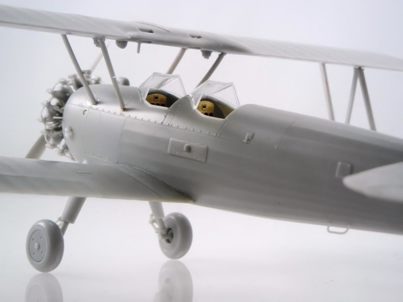
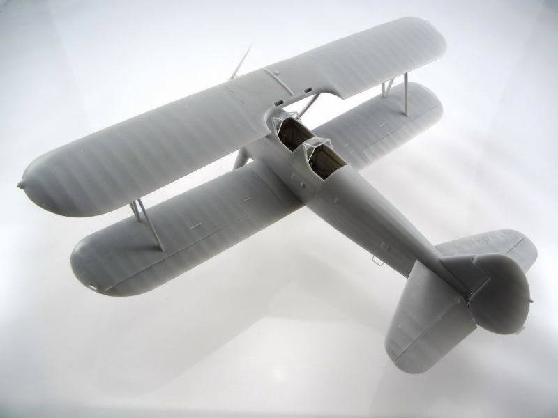
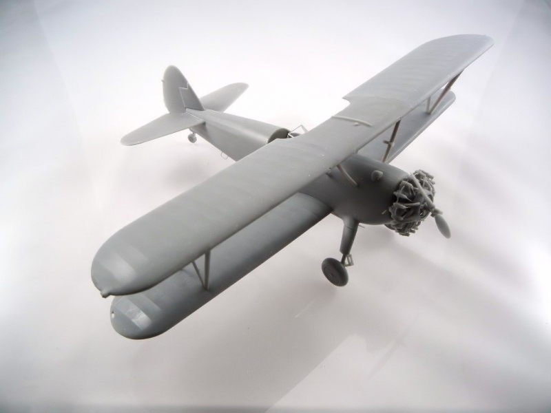
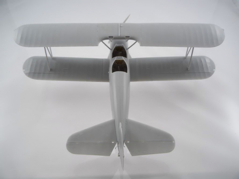
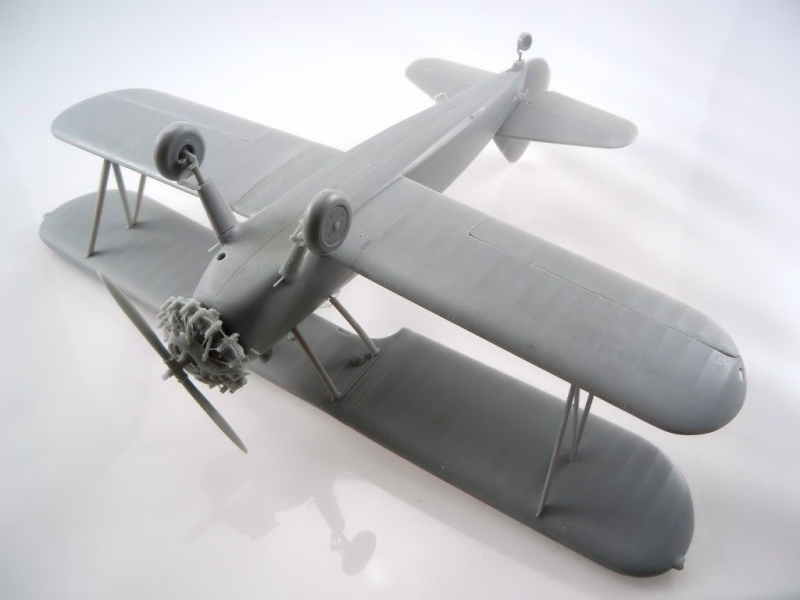
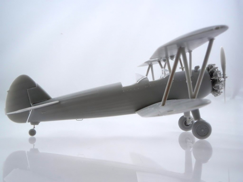
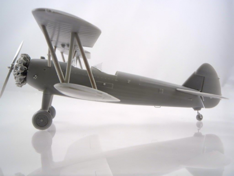
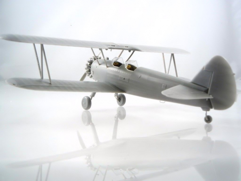
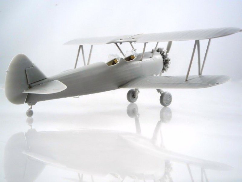
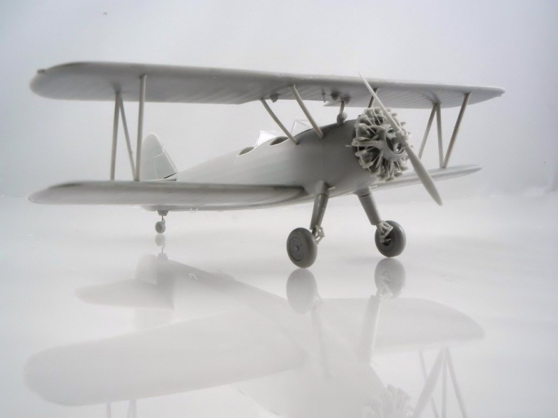
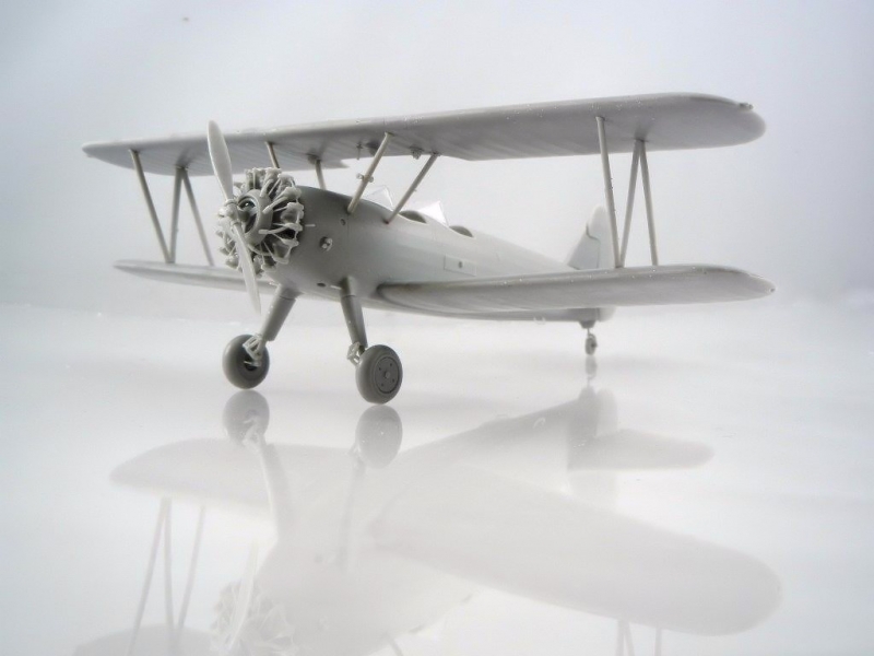
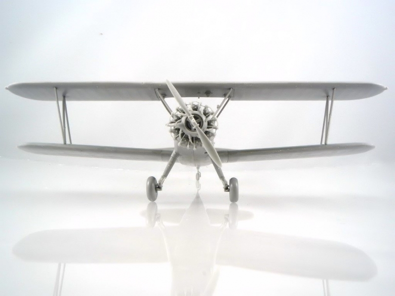
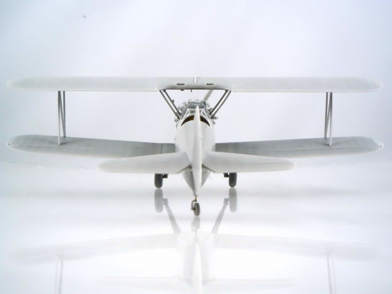
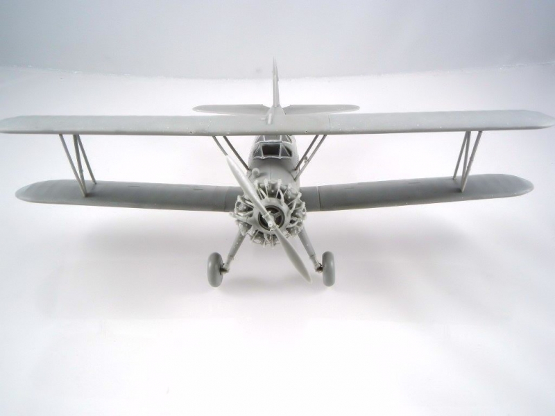
Congratulations on your newly finished model! Photos 39 ~ XX are of the completed model.
Doug Nelson
Photos and text copyright Doug Nelson (2014)
Gallery