1:32 Reggiane Re.2000 Heja/J20
 |
 |
 |
Silver Wings 1/32 Reggiane Re.2000 Heja/J20 build guide
Introduction
The subject of this build is an early test shot, so it should be noted that there may be small revisions in the course of the kit's production. The clear parts shown are not to full production standard. The purpose of the build is to test both the fit of parts and the assembly sequence shown in the instructions. At some points I will suggest changes to the sequence to reflect my own preferred way of working, but I recommend that you study the instructions carefully, because there is scope to tackle some areas in a number of ways. Obviously, you may want to modify the sequence further to take painting into account, something that's beyond the scope of this article.
As with any kit, short run or mainstream, the first job should be to check that all the parts are present and correct. The resin parts aren't numbered, so I found the simplest way was to work through the instructions step-by-step, visually identifying each piece and grouping them in small containers ready for each sub-assembly. Doing this also helps you become familiar with how the kit is designed and spot potential snags.
One point I noticed was that the test kit shown here included a pair of exhaust outlets which aren't shown in the instructions. Upon inquiring, Silver Wings informed me that they were originally cast integrally with the fuselage, but that they have since been included as separate pieces for a better effect.
The kit contains two photo-etched frets. The parts on the larger fret are numbered to match the instructions, whereas the parts on the smaller brass fret are not, and are simply indicated on the diagrams with the symbol “PE”.
The Engine & Propeller
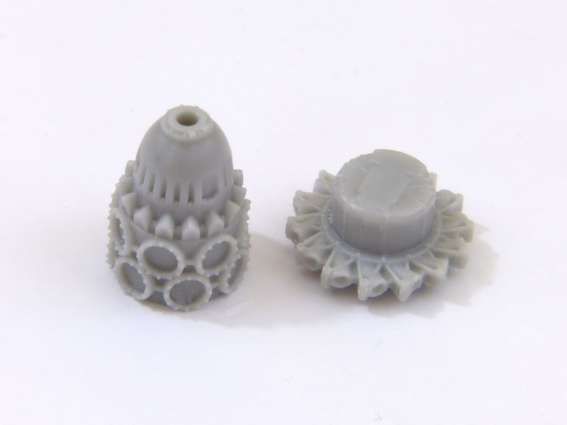
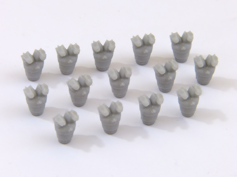
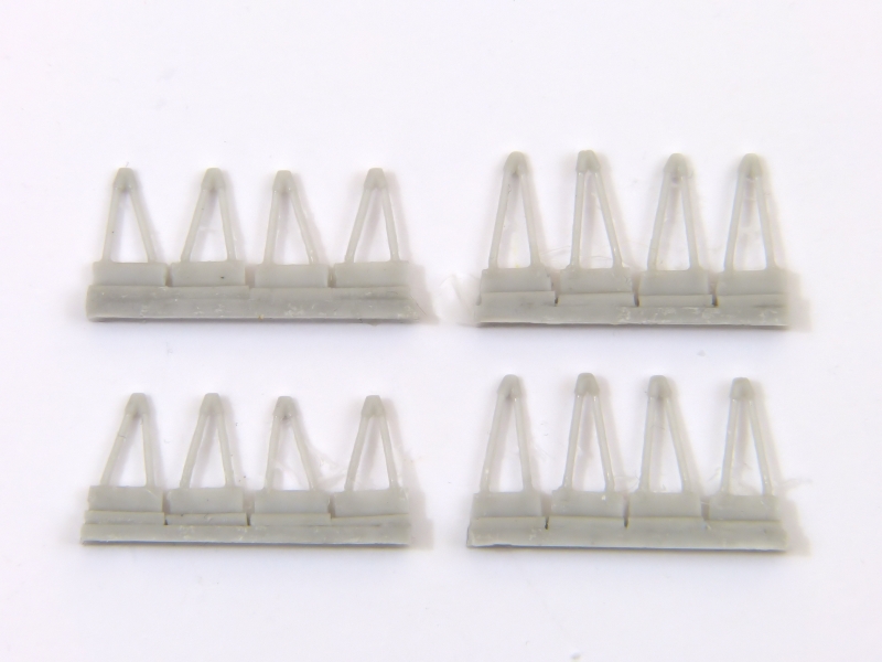
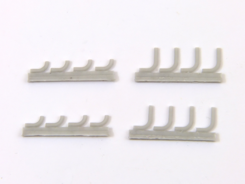
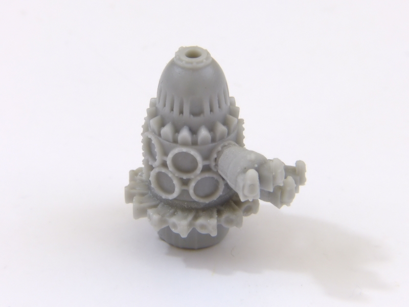
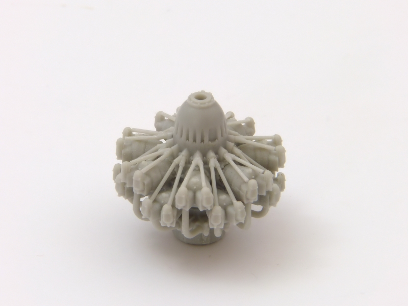
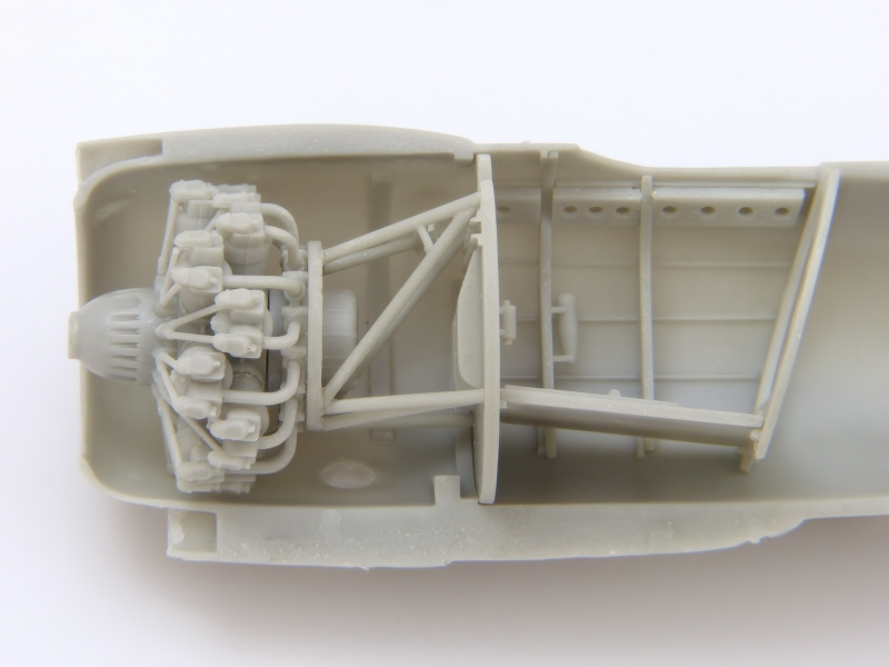
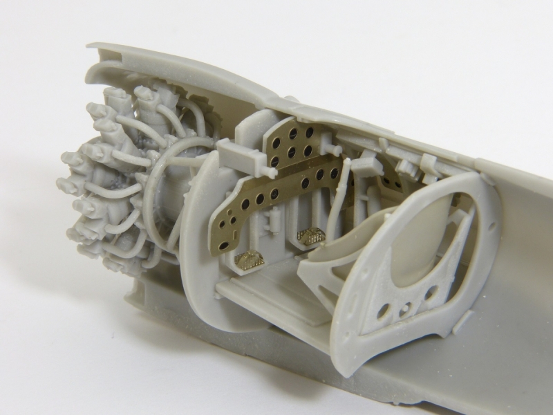
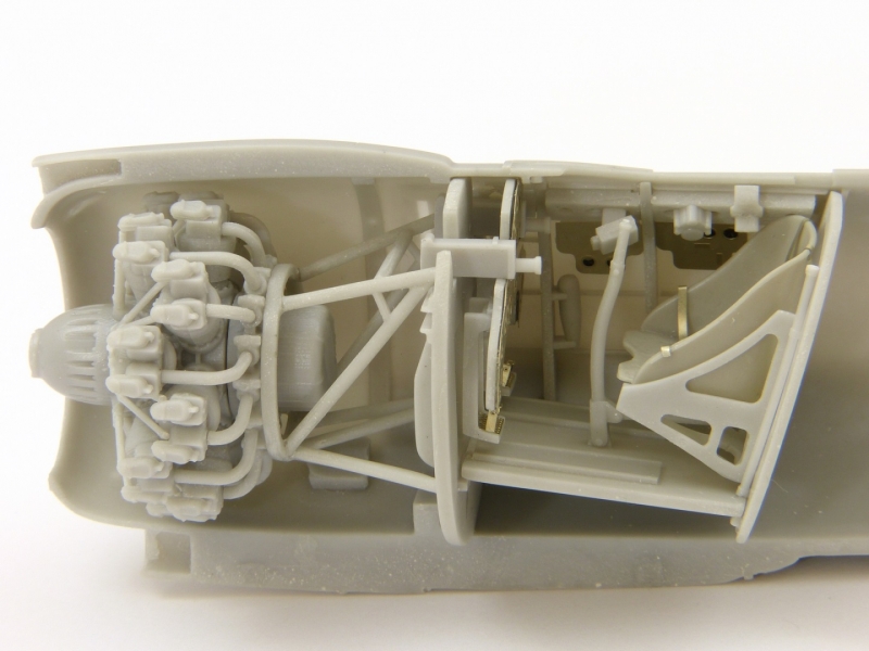
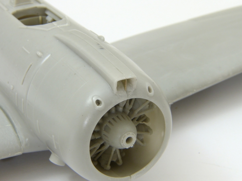
Construction begins with the engine, which is very nicely detailed with separate cylinders and intake pipes. You may choose to replace the pushrods with wire or plastic rod. If you use the resin parts, I recommend leaving a little bit of the casting plinth that you can reshape and trim down to ensure a precise fit. [photos 1-6]
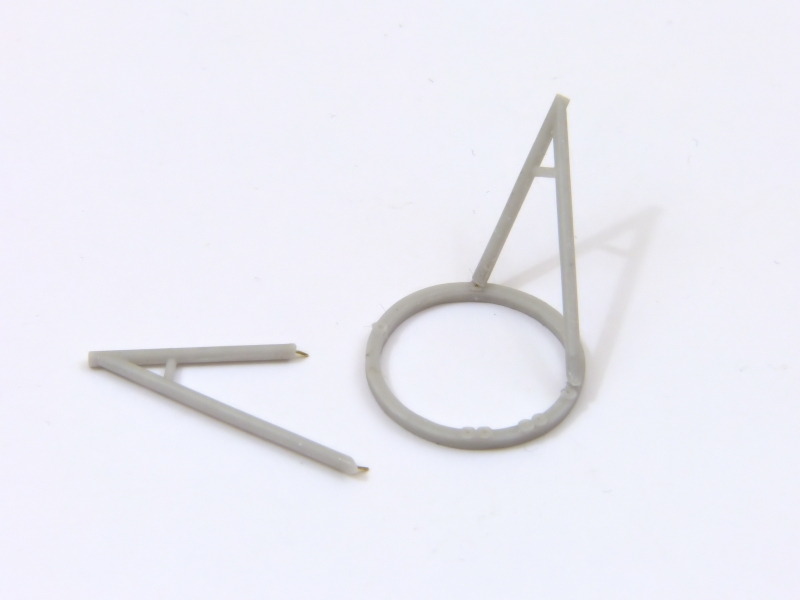
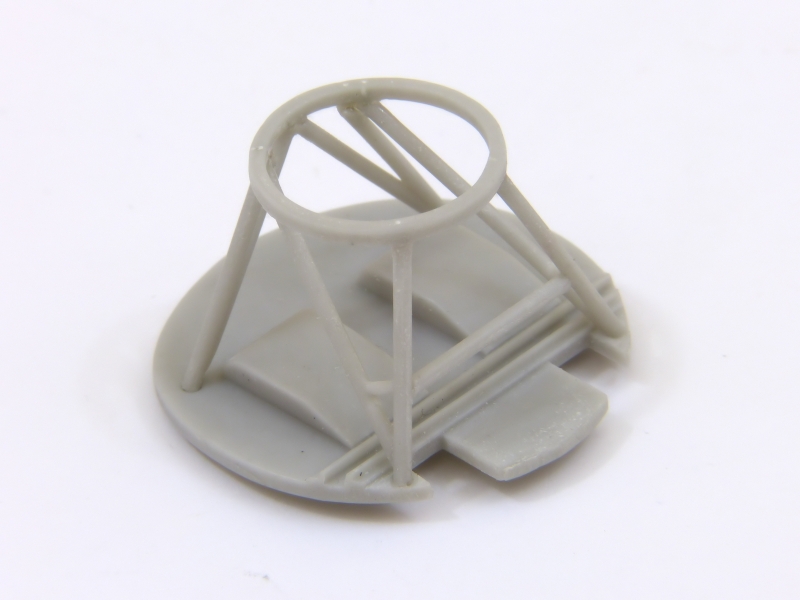
The engine mount is something of a cat's cradle to assemble. It's not overly complex, but is easy to build out of "true", so found it helpful to drill small holes and add wire pins to allow me to dry-fit it all together, using the firewall as a jig. Once I was happy that everything lined up correctly, I glued the joints. When it's complete, it's a surprisingly sturdy construction, functioning just like the original to support the engine. [photos 7-10]
The instructions indicate attaching the engine to its mount at this stage and this, in turn, to the firewall. I preferred to glue the mount to the firewall and left out the engine until I’d completed the cockpit. [photo 11]
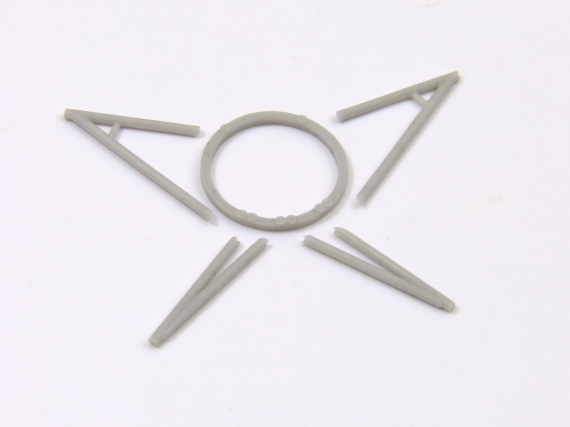
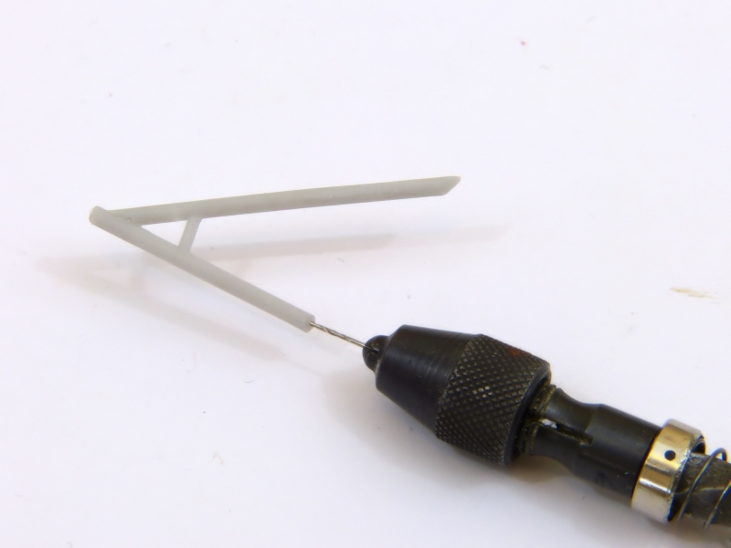
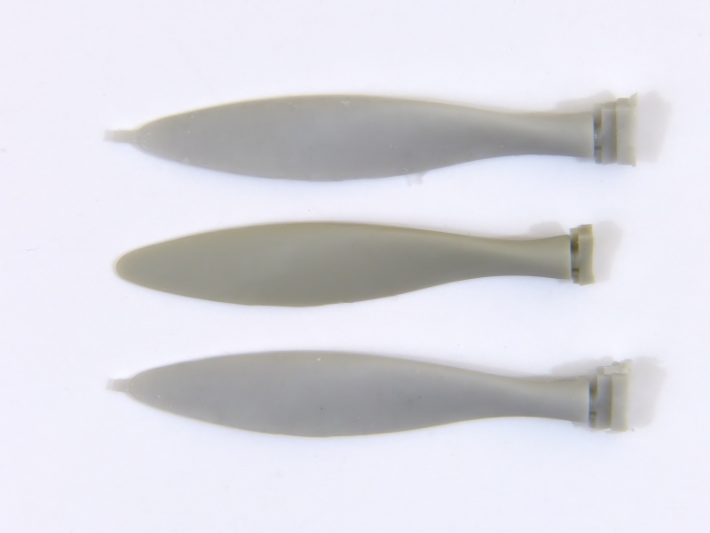
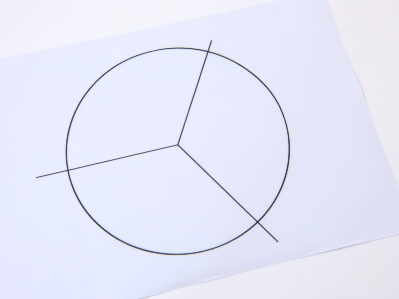
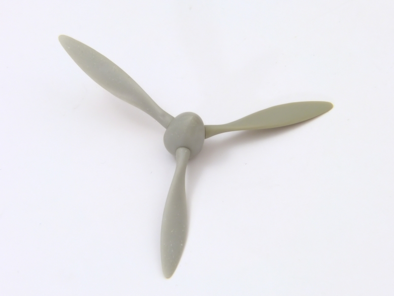
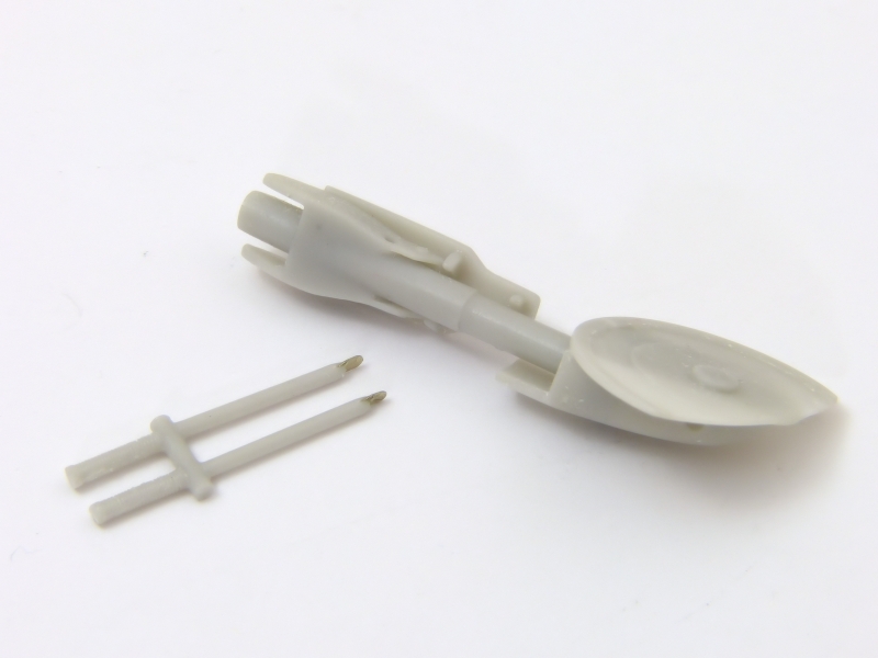
The instructions show adding the propeller now, but I left it until the end to avoid damage. The blades only have very short locating pins that can easily be lost in the process of removing the parts from their casting block, so I replaced them with styrene rod. To ensure the blades are set at the correct angles, I used a graphics programme to print a simple template with lines radiating at 120 degree from the centre of a circle. You could go one stage further and place small angled blocks on the lines to make sure each blade has identical pitch, but I was content to do it by eye. [photos 12-14]
Cockpit, Tailwheel & Fuselage
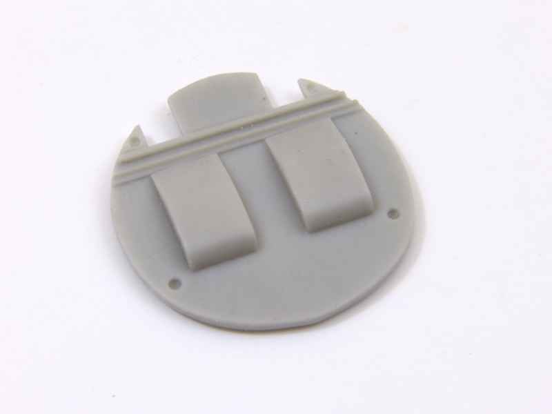
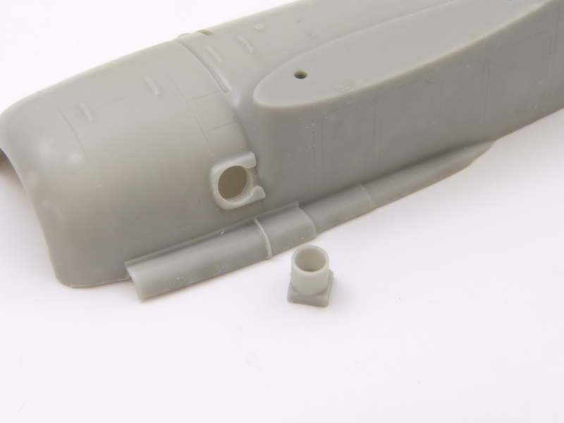
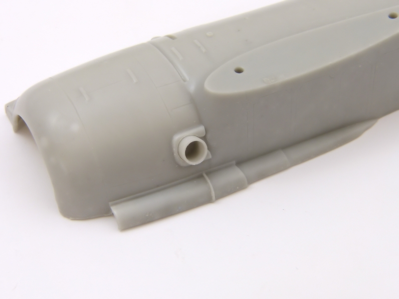
Before starting work on the interior, it’s wise to check the fit of the exhaust pipes. The holes needed opening up a little on my kit and this is easier done now. [photos 15-16]
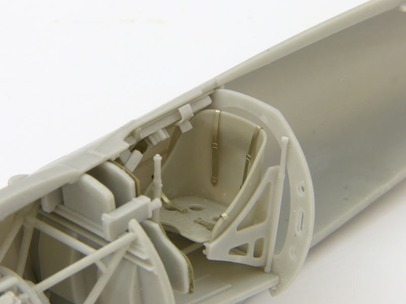
The kit contains everything you need to build a satisfyingly busy “office”, and it looks quite complex on the page because the instructions squeeze in a lot of information. The crucial first task is to establish the correct positions for the main components as a basis for fitting everything else.
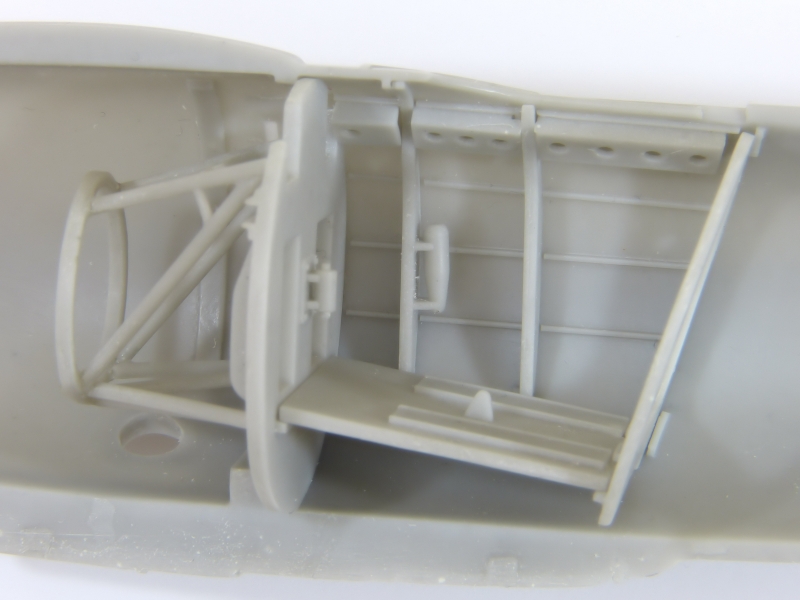
To get an idea of how the interior parts dovetail together, I started by dry-fitting the firewall, rear frame and the floor to establish their positions. With that done, I could be confident that the smaller items would fit around them. The rear frame leans backwards and the floor slopes up towards the front, sitting on the ledges on the rear of the firewall. When the firewall is sited correctly, the front of the engine just protrudes from the cowling. [photos 17-18]
Perforated channels fit between the side-frames under the cockpit sills, and a problem which I discovered later is that the front channels interfere with the machine guns. I trimmed them down when they were already in place, but forewarned is forearmed, and you could modify them easier installing them. [photo 19]
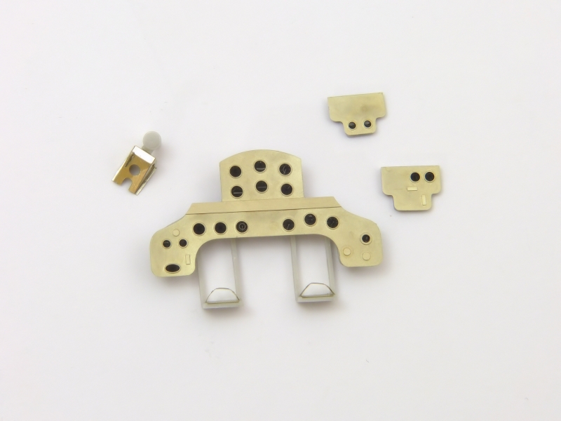
The instrument panel and side consoles are made up of photo-etched fascias with printed films for the instrument dials. These attach to a resin back to form a sandwich. The rudder pedals fit on the back of the main instrument panel and hang beneath it. Each has an etched grip and toe strap. [photo 20]
I fitted the side consoles as shown in the instructions, but the position of the main instrument panel is rather vague. Using the machine guns helped pinpoint the location, which ends up matching the diagram in the instructions, tucked in behind the side-frames which partly obscure the lower instruments. That does seem odd, but it positions the rudder pedals correctly in front of the orifices in the firewall. [photo 21]
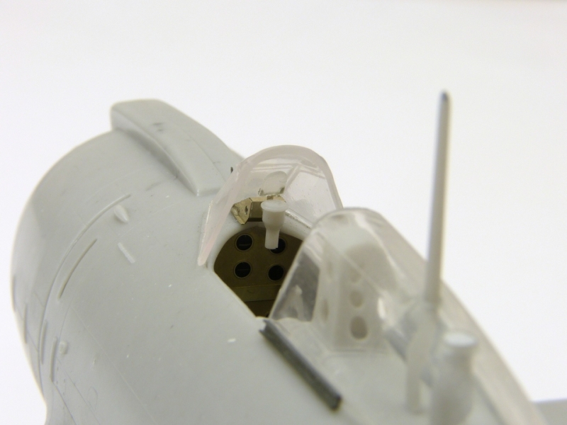
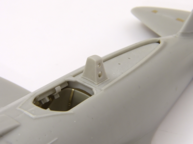
The gunsight comes complete with a photo-etched mount to fold to shape and a clear resin reflector. The instructions appear to show the mount behind the instrument panel, with the reflector in front. This simply won't work, because the cockpit coaming is in the way. Instead, I chose to attach the mount on top of the coaming, which seems more logical and sets the sight at the correct height. I left it off at this stage to avoid damaging it, only installing it when I was ready to fit the windscreen. [photo 22]
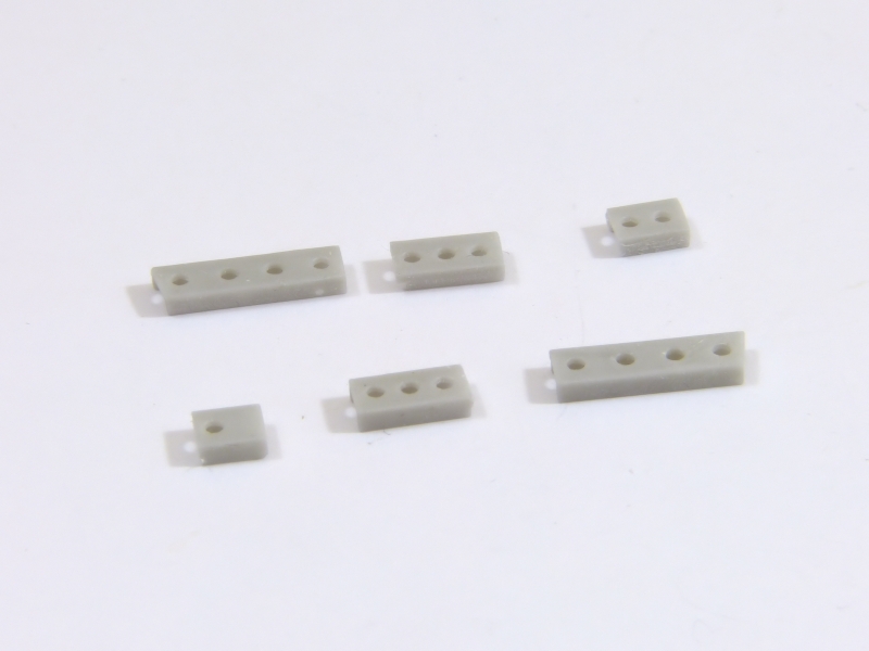
The throttle unit looks pretty complex on paper because each lever is made up from three etched parts. Two of these are actually thickeners to build up the knobs, so you could simplify things by just applying a drop of white glue to form each knob. [photo 23]
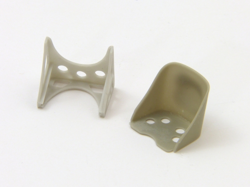
The seat fits in its mounting frame neatly, which in turn attaches to a pair of rods. An etched harness is provided, but it does seem rather undersized, so you may choose to replace it. [photos 24-25]
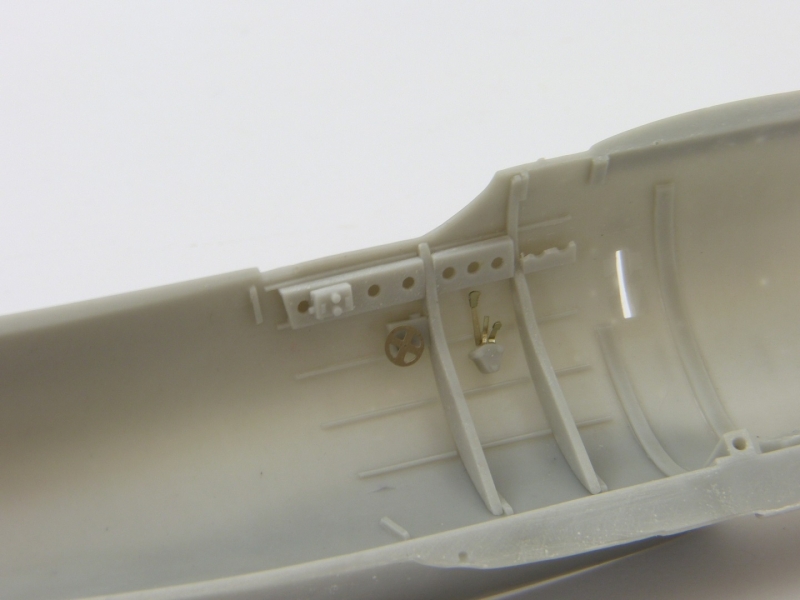
Attach the control rod to the base of the joystick and glue the column to its mount on the cockpit floor with the control rod passing under the pilot's seat. [photos 26-27]
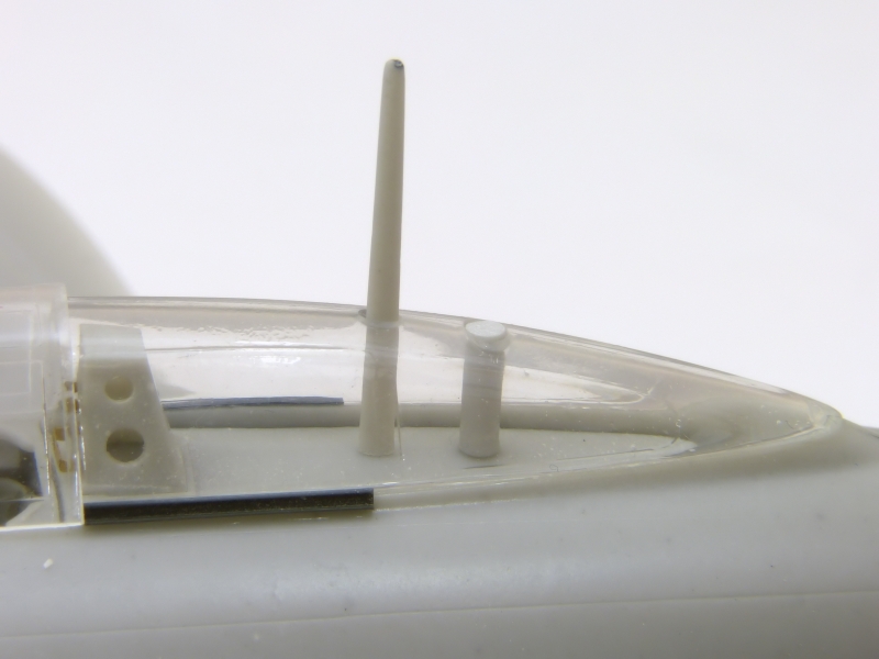
The rear decking can be built in three styles, depending on which nationality aircraft you opt for. The parts are designed to cater for all three options, so you'll need to fill holes as appropriate. Check the alignment of the radio mast and the fuel tank filler pipe behind it. I left the rear decking loose at this stage to avoid the aerial mast getting knocked. You can slot it in without difficulty after the fuselage halves are joined. [photo 28]
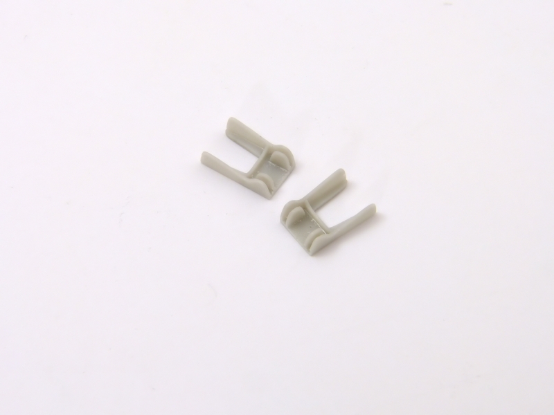
The small brass etched fret provides a pair of brackets to fit on the headrest. They don't look at all comfortable and I pity any pilot who had his head bashed against them! I found them too large to fit as shown in the instructions, so I took the shorter one and mounted it at the base of the headrest and then cut down the long one to fit it at the top.
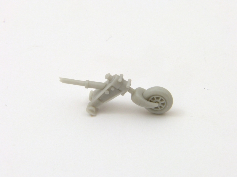
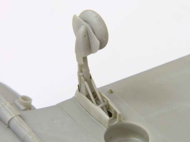
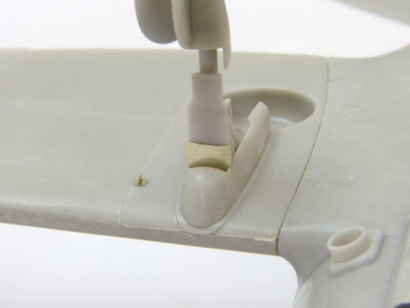
You could install the tailwheel before joining the fuselage halves, but risks it getting knocked during later assembly, so I assembled it and just checked the fit and left it off until I’d attached the wings and tail. The strut attaches to two small brackets that mount on the front wall of the tailwheel well. [photo 29]
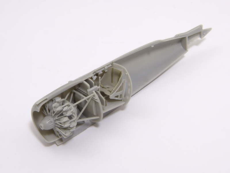
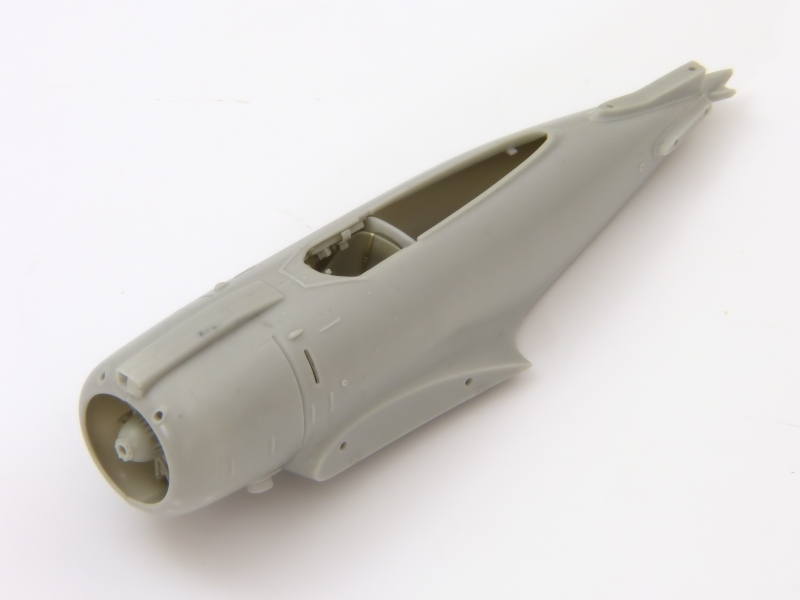
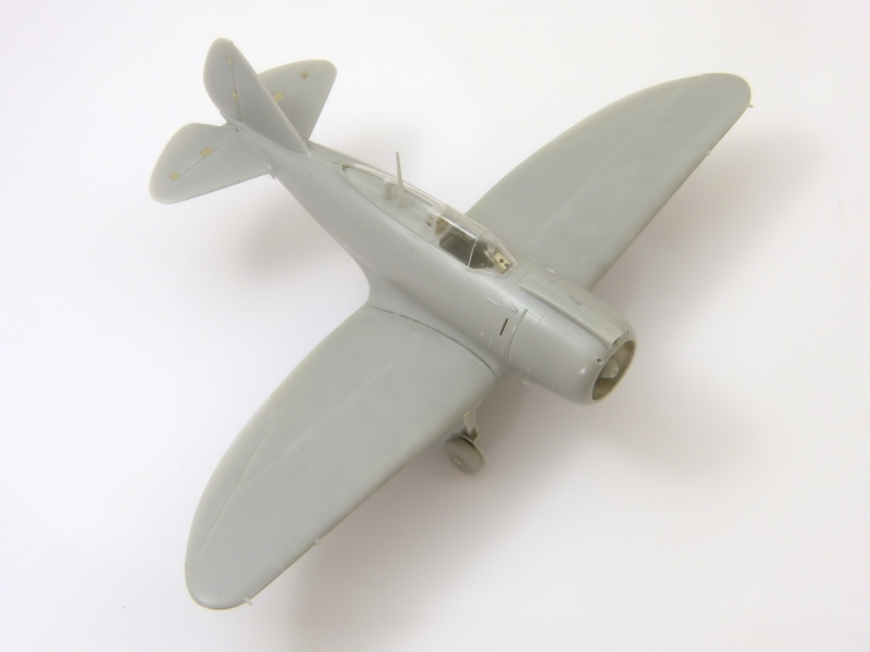
After one last check to make sure I hadn’t forgotten any interior parts I installed the engine and glued the fuselage halves together. Once they were dry, I cleaned up the opening for the intake above the cowling ready for its photo-etched splitter. [photos 30-31]
I fitted the vertical fin, but left off the rudder until later.
The instructions indicate to fit the canopy in place at this stage, but I preferred to leave it until I’d finished work on the wings and tail.
Wings & Undercarriage
The instructions indicate to build and fit the undercarriage before attaching the wings to the fuselage, but I always prefer to complete the main parts of kit’s airframe before adding parts like these which are easy to damage.
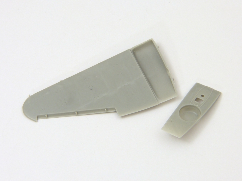
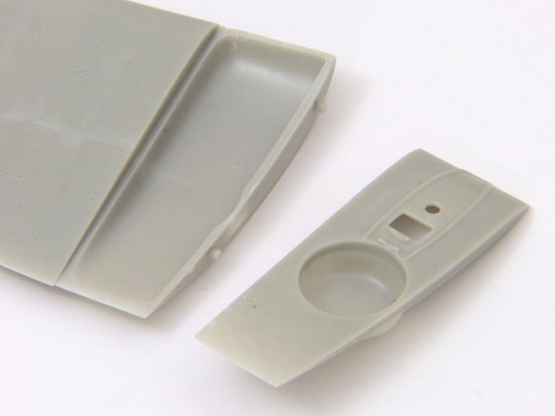
The wheel wells are cleverly designed to avoid problems with casting. The wells themselves are cast along with the innermost section of the underside of each wing as a drop-in panel. This also leaves an open bay for the retraction arms. The fit is excellent. [photos 32-33]
I found the wings a good tight fit at the roots - but there's a snag. Getting the best overall fit created too much dihedral. Looking at photos of the full-sized aircraft, there's only a small amount of dihedral evident, so I tacked the wings in place with CA at the correct angle and then filled the resulting gaps with 5-minute epoxy glue for strong joints.
With the wing joints dry, I fitted the ailerons. Each hinge has a pair of etched faces. I attached these after the ailerons were in place as they might interfere with the fit. [photo 34]
Once I was happy with the wings, I turned to the horizontal tail and attached it (minus the elevators), checking that everything was square and true.
My kit lacked a clear tail light, so I attached a small piece of clear styrene and filed it to shape. With that done, you can fit the elevators and rudder without fear of knocking them. The hinge covers are supplied as photo-etched pieces. I found them slightly too large for the cut-outs, so I spent a few minutes adjusting them. I attached the control surfaces first, using the cut-outs to position the hinges. [photo 35]
Once you're happy that the main airframe is complete, you can think about fitting the undercarriage.
I installed the tailwheel first, attaching the brackets in the marked locations. With that done, the tailwheel doors can be fitted. [photos 36-37]
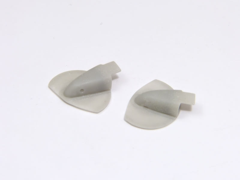
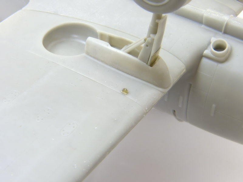
The mountings for the undercarriage legs are handed, being angled to compensate for the wings' dihedral, so make sure to get them the right way around. The same is true for the fairings for the gear legs. The deeper side should be outboard. [photos 38-39]
The undercarriage legs should have the flat face on the front. Glue them firmly to the lower sections, making sure they are set at 90 degrees to the wheel covers and allow them to dry well. [photos 40-41]
You need to attach a tiny etched tip to the end of each retraction arm. As there’s very little gluing surface and they’d be likely to snap off, I cut tiny slots for them with a fine razor saw. This allows stronger joints. [photo 42]
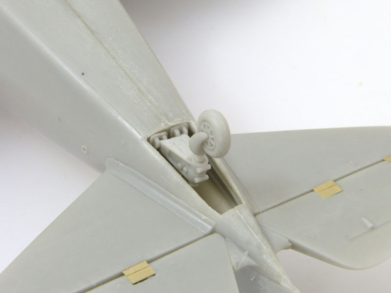
Each leg attaches to the pair of mounting brackets, with the retraction arms tucking to the rectangular hole behind them. Ideally, use a slower-setting CA or an epoxy glue to allow a little bit of working time to ensure that you have the legs lined up correctly. [photo 43]
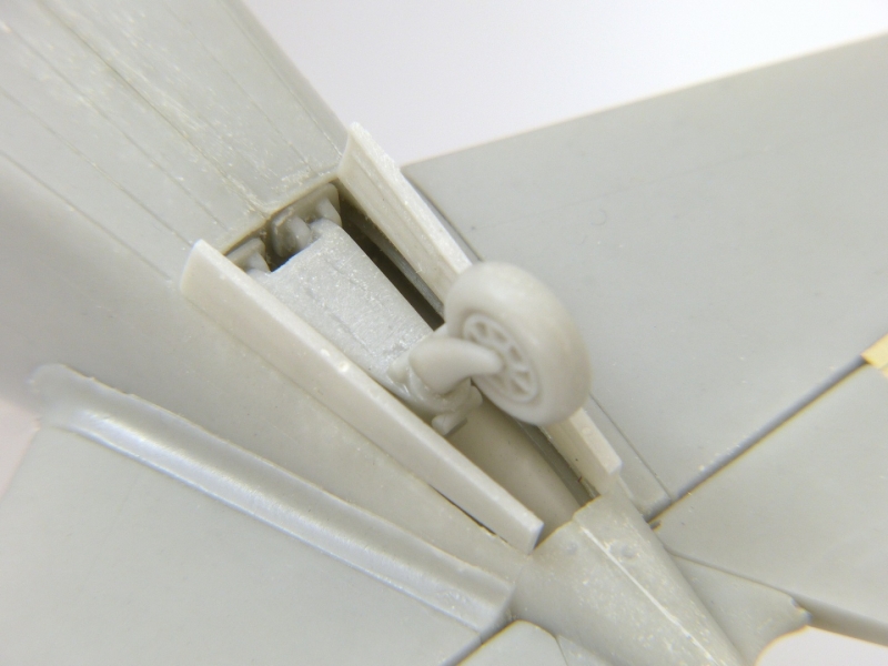
Small gear doors are supplied as etched parts. You should curve these slightly to match the contour of the main leg covers and the gear housings. [photo 44]
The mainwheels attach onto very short "axles", but they are quite sufficient for the task. When you've removed each wheel from its casting block, you may want to file a slight "flat" on the resulting scar and position them to give the effect of weighted wheels.
With everything dry it’s time for the moment of truth! Standing the model on its wheels. Be careful - it's pretty heavy - but the undercarriage is sturdy and well able to take the weight.
The canopy
The canopy is cast in three sections. Take note that the sliding section of the canopy has the thickest frame on its rear edge. [photos 45-46]
If you’re building a Hungarian aircraft, there’s a mirror to fit on the windscreen, while all three versions have a lock/grab handle to install at the front of the sliding section. Unfortunately, the etched part is much larger than shown in the instructions and won't fit where indicated.
The rails for the sliding centre section are supplied as etched parts which much be folded into U-channels. If you pose the canopy open, fix the rails on the cockpit sills. I the canopy is closed, they fit either side of the fixed rear section.
I have to admit the canopy rails defeated me. Despite my best efforts, I couldn't bend them to a true U-section. Even heating them in a gas flame to soften the metal didn't help - there simply wasn't enough material to get the leverage needed to bend them neatly. So, I did the obvious thing... and cheated! I used them as templates to cut lengths of U-section styrene channel and thinned it down a bit. While it looks a bit heavy compared with the metal parts, it’s a passable solution if you struggle as I did. [photo 47]
Final Details
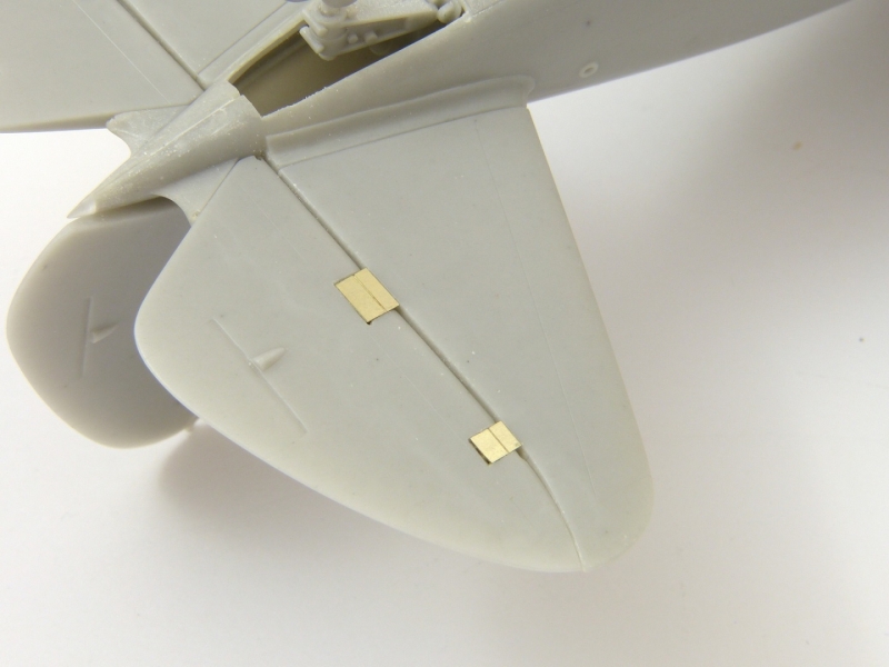
The instructions show small photo-etched hooks and rings fitting to the top surface of each wing. I couldn't see any sign of these in the walkaround of the Swedish aircraft and I suspect they are lifting points that were used to hoist the naval version of the Re 2000 onto its catapult for launching, so I omitted them. On the underside are what are may be tie-down rings, so I did fit those. [photo 48]
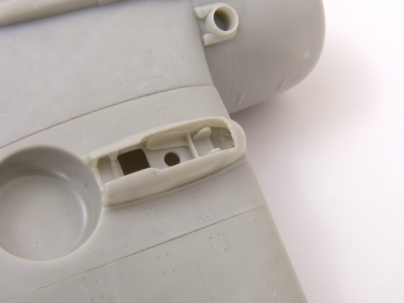
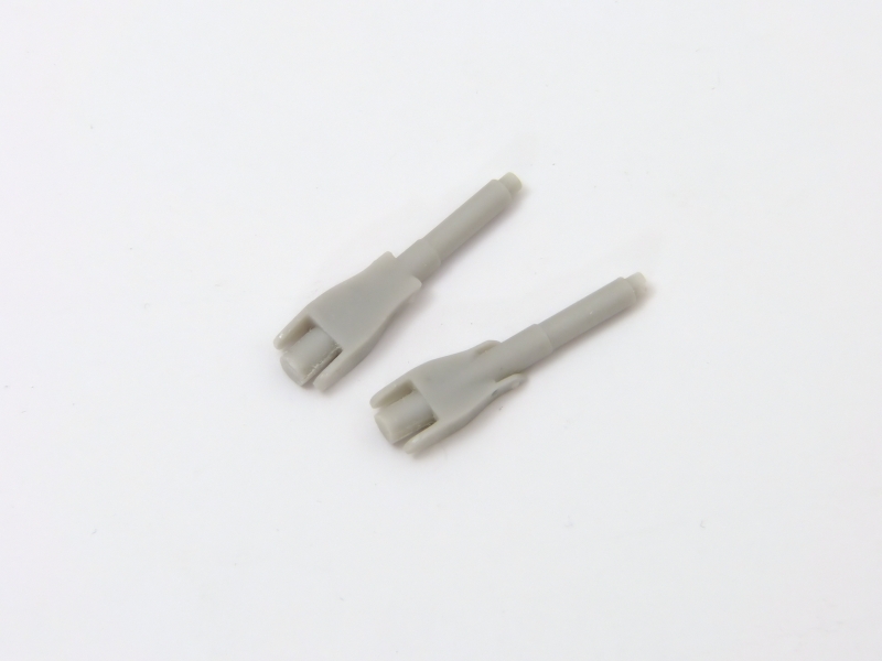
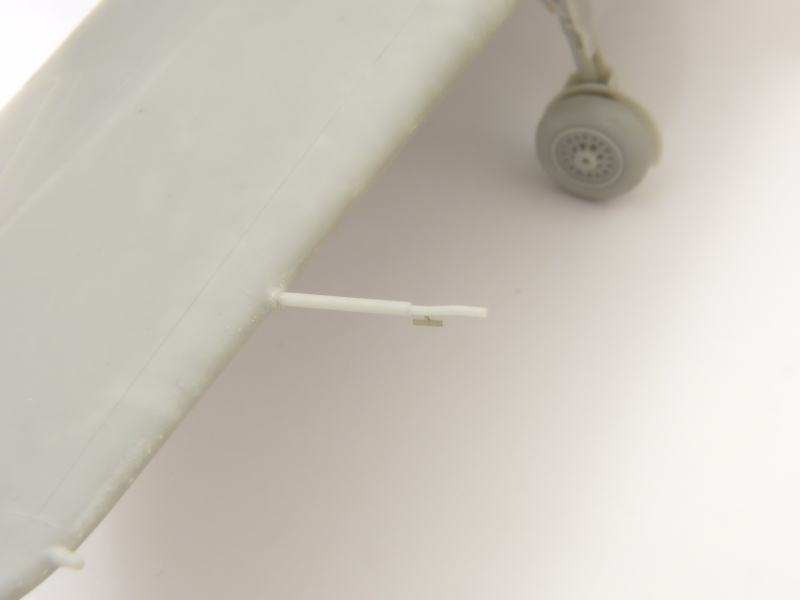
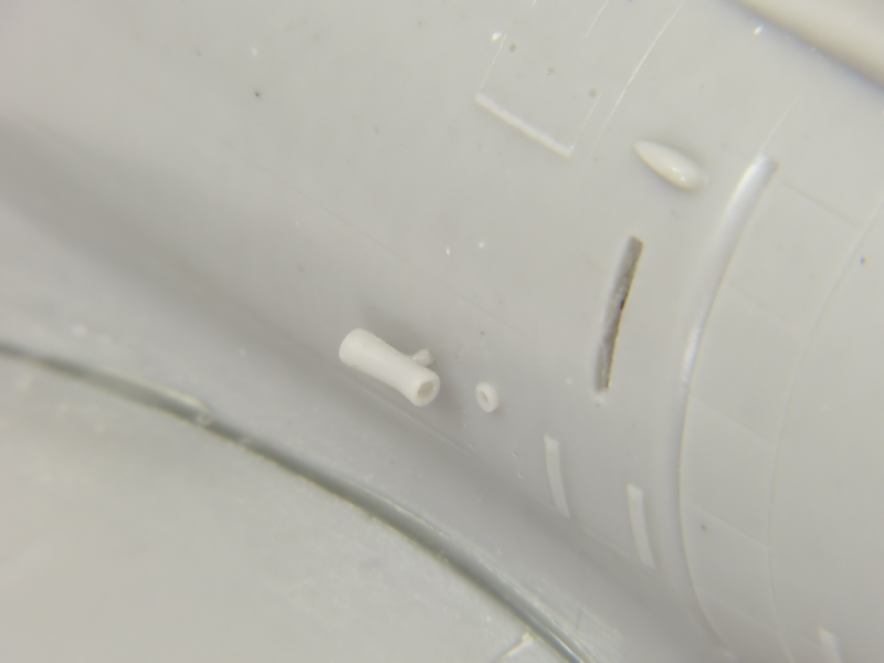
Somewhat unusually, the Re. 2000 sports two pitot tubes, one on each wing. The longer one attaches to the starboard wing as per the main diagram in the instructions (the position is shown reversed in the two smaller views), and a small etched vane fits on its kinked front section. The venturi attaches to the starboard fuselage side and its longer end should face to the rear (not as shown in the instructions). [photos 49-50]
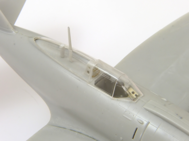
The last task was to glue the external bead sight in front of the windscreen before fitting the propeller and declaring the model finished. [photos 51-53]
Conclusion
Overall, I found Silver Wing's Re 2000 a very satisfying build. It offered a few challenges in places, but that's half the fun of modelling, and the result is very impressive, capturing the look of this attractive aircraft nicely.
Rowan Baylis
Photos and text copyright Rowan Baylis (2018)
Gallery