1:32 Gloster Gladiator Mk I / Mk II
 |
 |
 |
Silver Wings 1:32 Gloster Gladiator Mk I / Mk II build guide
Parts Cleanup
As with other Silver Wings kits, parts cleanup is fairly simple, and due to the soft resin they use for their kit, a sprue cutter can even be used to snip most parts from their pour stubs. After that, a few scrapes with the Xacto knife and/or sanding stick and the part is ready for use.
With these kits, since there are no part numbers to worry about, I like to clean up all the parts and then begin the build. Any parts can be painted as appropriate after cleanup and before assembly as well. A few things to note when preparing your kit parts for use:
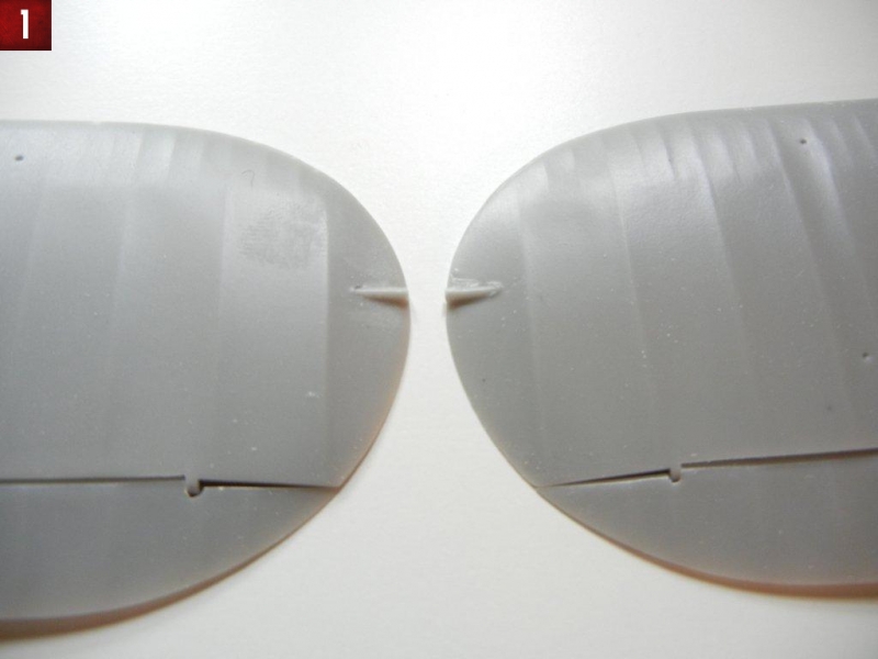
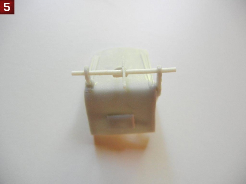
- The lower wings have a couple of excess resin “rods” on the top tips (see photo 1), these must be removed as the outer wing should be smooth.
- The ailerons on my kit did not want to fit to the wings at all. Upon investigating, they seem to have had a slight shift during molding, as there was a slight step inside each of the hinge attachment points. Cleaning these up led to a much better fit.
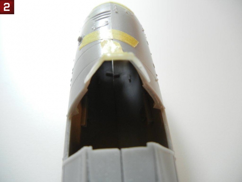
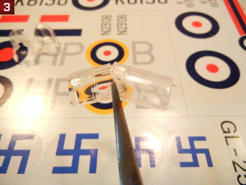
- The windscreen for either version (Mark I shown in photo 2) is too splayed out at the base. To fix, simply pour hot water on the windscreen and bend inwards to get the correct shape. Once complete, I recommend dipping all the canopy parts in future, as it will greatly improve their transparency (see photo 3)
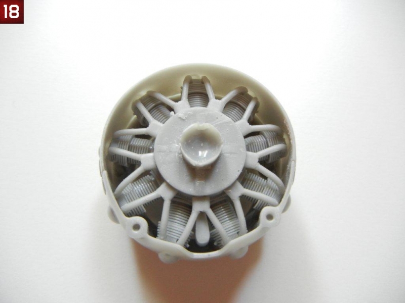
- The engine block has a pour block on the backside, and you should only remove the “fins”, leaving the center round part as this will be needed to attach the engine/cowl assembly to the fuselage (see photo 18 referenced later in the guide)
- The lower cowl piece and upper appear to be different sizes. However, once assembled and fitted to the exhaust collector ring (the round front cowl part) they will assume the correct shape. Also note that the lower cowl has the cutout for the carb intake common to the Mk.II Gladiator, which is not always correct for a Mk.I airframe. Consult your references for the markings you plan to do, and if necessary, the cutout can be filled with a piece of sheet styrene (do so after fitting to the lower cowl to the front exhaust collector ring to get the correct shape).
- My cockpit frames were a bit twisted and broken in some spots, so I repaired the breaks before assembly. Note that the shape of these frames should “bow out” in the middle.
- The lower cowl ring has two pins that are used to fit it to the exhaust collector ring, take care not to remove them when cleaning up the pour stubs that are near them. Also be sure to take care when removing the pour stubs from the front edge of both the upper and lower cowl, in order to keep a straight edge. The exhaust collector ring has two bulges under two of its three pour stubs so take care not to sand them down too much either.
- The starboard side of the seat needs some cleanup from the pour stub, but try not to destroy the lip surrounding the seat pan.
- The engine cylinders have some slight seams on the sides that may require cleanup, however any that you miss will likely not be visible on the finished model without searching really hard for them. Be sure not to damage the exhaust tubes that face forward on each cylinder head. Also note that the pushrods need to be cut carefully, and err on cutting them too long as if you just snip them off like I did, you will find that many of them are a tad short.
- The kit provided Fairey-Reed propeller will need some work to make it useable, as it is the same thickness on both edges of the blade, and lacks most of the twist at the base of the blade that is visible in many photographs (it’s just started on the kit part). Fortunately, you can sand the trailing edge thinner easily (since this is softer resin), and the twist at the base can be enhanced after heating the blade in hot water.
- There will be some extra parts depending on which version and airframe you wish to model, so not all parts will require cleanup if you know which version/airframe you plan to build. I also noted some “spare” duplicates of some fragile parts in my kit, which is a nice touch by Silver Wings.
Engine Assembly
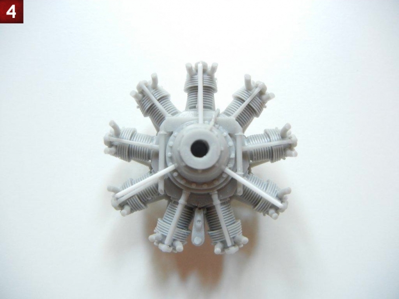
Prior to assembling the engine, you should drill three 1mm (#60 drill bit) holes, one each at the 12:00, 4:00 and 8:00 positions in the gear cover (see photo 4 for location) for the cowl brace (referred to in the instructions as “prepare on your own”). This brace is actually 3 parts on each brace, one rod from the gear cover to the exhaust collector ring (the front part of the cowl) and two thinner rods from the each side the cylinder head base to the main brace, attaching just below where the main brace meets the exhaust collector. For purposes of this build, I just added the three 1mm rods.
Once you have drilled your holes, engine assembly begins with the cylinder heads. Attach each one, making sure it is facing directly forward. You can check your work by putting them up against the exhaust collector ring.
After this, you can attach the pushrods in place; each has a pad on the engine block and the cylinder head to aid in placement. If you are building a Mk1 airframe, you should attach the two downward pointing tubes referred to in the instructions (see photo 4 for location assistance)
Finally, attach the breather tubes to the back of the engine block and cylinder heads.
Interior Subassemblies
- Assemble the throttle as shown in the instructions, the two handles are provided in resin, and just need some careful cleanup.
- Paint the back of the Mk.I or Mk.II instrument film white. On my kit, the Mk.I instrument panel was almost 1mm too wide, so either trim it now, and/or you can thin the cockpit sidewalls where they contact the instrument panel to help ensure a good fit. My references indicate that the panel (either Mk.I or Mk.II) should be black (and it is in many photos), however some preserved airframes show them in a red-brown Bakelite color. Once the white paint is dry, you can attach the film to the back of the appropriate panels. Silver Wings also provides a nice brace for either panel, which makes it much easier to attach to the completed cockpit. The brace should be interior green, and once dry, attach your PE panels in place as appropriate.
- Assemble the ammunition box (two parts to the base plate), but do not attach the chutes until you are ready to close the fuselage in order to get them at the correct angle to meet the gun breeches.
- Assemble the rudder pedals, and attach them to the floorboard. For best results, I bent the PE toe straps around the metal end of a paintbrush, as the PE buckle area does not want to bend as nicely as the rest of it.
- Cleanup and attach the compass pedestal to the floorboard. If you have a decal for a compass, you can apply it after painting for a more realistic look. I left my control stick off until after the cockpit was assembled to make it easier to place the floorboard in the cockpit framing.
- I found it easier to attach the two brackets to the appropriate sides of the seat, rather than trying to get them in the exact position on the 24mm rod as indicated in the instructions. After the two brackets had set, I put the rod through the appropriate holes, with the bell crank between them. I then centered the bell crank on the rod between the brackets and glued it into position. I did not glue the rod to the seat brackets, as that will allow me to position the seat in the center of the cockpit later (see photo 5). You may also want to attach the seat harness straps to the bottom of the seat before placing it in the fuselage later.
- You can attach the two cylinders and battery to the rear floorboard.
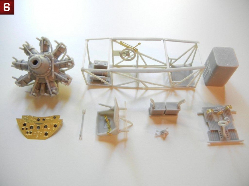
- Photo 6 shows the completed subassemblies (including the cockpit frame and engine)
Cockpit Assembly
The Gladiator cockpit is primarily interior green with throttle, etc. in black. Assembling the interior for this kit is relatively straight forward, and like other Silver Wings kits, getting the cockpit framing assembled as straight as possible is key. I began building up the interior subassemblies by working on the cockpit framing. For best results, I recommend the following order:
- Using square styrene strip, cut two 22mm pieces, one 17mm piece and one 24mm piece.
- Align the two side frames with each other, and glue the center “H” frame to each side in the position indicated by the instructions.
- Immediately glue the “V” frame to each side in the position indicated by the instructions (note that it should slant back slightly to align with the side frame), followed up the middle-front 22mm styrene piece and the 24mm styrene piece (note that this piece should be fitted immediately behind the sill flange area, otherwise your cockpit will be too wide)
- Double-check your alignment to ensure everything is square (note the cockpit should be narrower at the bottom than the top).
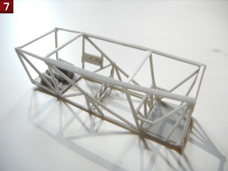
- Next, you can attach the front and rear floor pieces, followed by the two remaining upper styrene pieces (17mm and 22mm). See photo 7.
- Test fit your completed cockpit frame to the fuselage to ensure it fits properly.
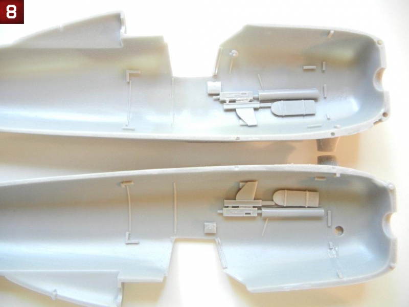
- Now is a good time to attach the required parts to the fuselage side pieces (photo 8). I elected to omit the front bulkhead as test fitting showed that it was not necessary.
- Next assemble the remaining cockpit components to the frame. Start with the floorboard, which should rest on the “V” frame in the front, and the tabs on the side frames just above the “H” frame in the back.
- Attach the bottom seat rod (with the seat) to the cockpit sidewalls, resting it on top of the tabs as indicated. I did not glue the top back part of the seat to the upper frame, allowing it to move forward for the time being (which will be helpful in installing the backplate later).
- Attach the trim wheel and the PE control lever assembly, as well as the throttle and round switch box as indicated by the instructions.
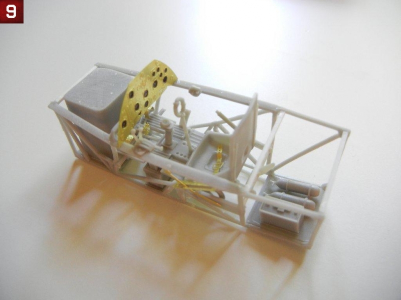
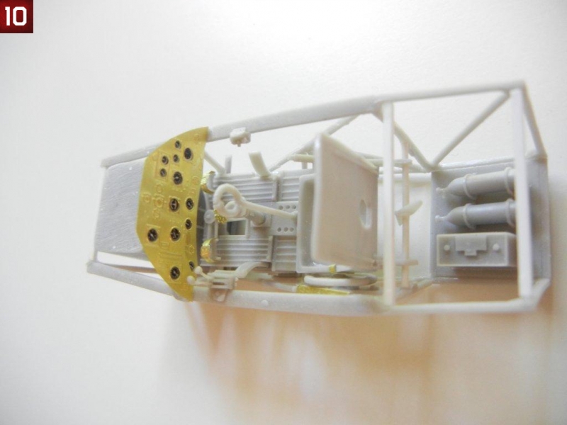
- Attach the fuel tank to the front floor, the ammo bin (dry fit in the fuselage side and use your installed MG's to get the correct fit) and the instrument panel appropriate for your model (see photo 9 and 10)
Fuselage Assembly
Fuselage assembly is straightforward, as one would expect, simply insert the cockpit assembly between the fuselage halves and glue together. There are alignment tabs in the fuselage to help align the cockpit properly. I chose to leave mine "loose" and tacked it in place once the fuselage halves were together.
- Once your fuselage glue is set, you can clean up the seams.
- Moving your seat back forward (pivoting on the lower rod), insert the rear backplate, taking care to center it within the fuselage. Once the fit is correct, you can glue it into position, followed by the seat back once the backplate is set.
- If you are going to attach either of your side doors in the closed position, do so now. If either will be open, they can be added later.
- Next, attach the seat harness tray, and the upper seat harness straps (the tip of the harness should be just through the slot in the backplate), then attach the other side strap, and final cap with the small PE attachment plate. Finally, attach the two tensioning springs (PE7) to either side. Mine were a little long, so I trimmed them to fit.
- I then attached the gun sight frame pieces, followed by the gun sight with the appropriate film.
- Attach the front windscreen and rear canopy at this point being sure to center them on the fuselage. If you plan to have your main canopy closed, you should use it to get the proper position of the windscreen and rear canopy to optimize the overall canopy fit.
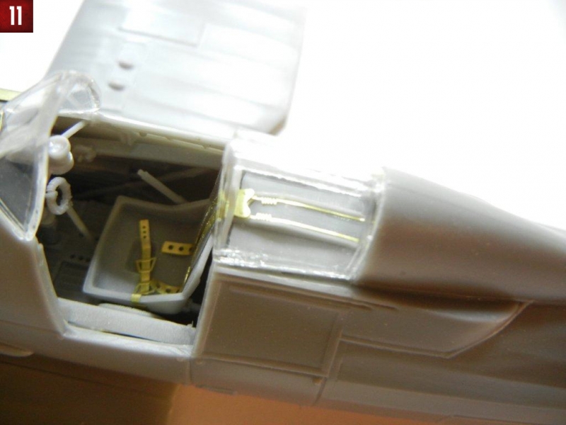
- Once dry, test fit the brace that attaches between the backplate and top of the rear canopy. I needed to sand mine slightly, and then attached it in position. (see photo 11 and 12)
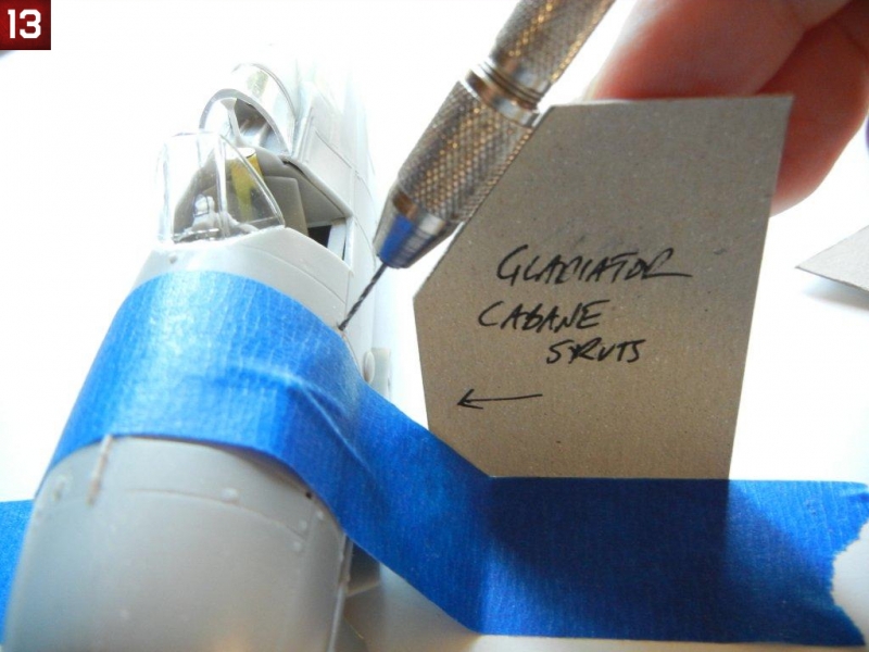
- I then took the opportunity to drill out the cabane strut attachment points, after making a drill guide template (see photo 13).
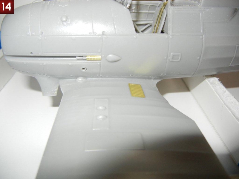
- Assemble the fuselage MG's and attach as indicated in the instructions. I believe that the longer MG barrels should go on the fuselage, but can't be sure (I used the shorter ones on the fuselage for this build - but the longer ones look too long on the wing). Bend parts PE14 into the correct curved shape (I used the handle of a paintbrush, and then bent the inner rear parts in past the vertical for the best fit) and attach as indicated (photo 14). Note that they highest part of PE14 should be just about flush with the fuselage.
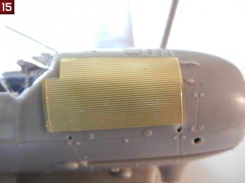
- Bend the radiator mat to fit the curve of the fuselage (I rolled an Xacto handle on mine to get the correct shape). Note that there should be a slight space between the mat and the fuselage. the kit has 4 raised attachment stubs molded to the fuselage. Test fitting the mat showed that these left what I felt was too large of a gap for my tastes, so they were sanded down slightly. I then glued the radiator mat into position. Attach the small rod (vent?) to the hole in the top of the fuselage as indicated in the instructions (see photo 15)
Cowling Assembly
You may want to pre-paint the interiors of the cowls and exhaust collector ring, and touch up as necessary after assembly. After studying the parts, I came up with the following assembly sequence to get the cowl together:
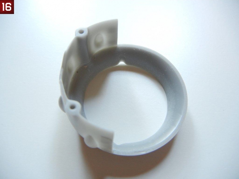
- Attach the lower cowl piece to the exhaust collector ring (the front of the cowl), taking care to get it aligned properly (see photo 16).
- Once dry, test fit the completed engine to the exhaust collector ring. You will likely have to apply some pressure to get a good fit - be careful not to press too hard or you may break some of the cylinder exhaust tubes (ask me how I know this)! Sand any cylinder exhaust pipes that do not fit properly.
- Once you are satisfied with the fit (and the engine is square to the exhaust collector ring), glue the engine to the exhaust collector ring using the exhaust tubes on the cylinders. Note that these pipes were welded to the exhaust collector ring on the real aircraft, so you do not need a perfect attachment, some superglue gel around the pipe to represent the weld is fine :)
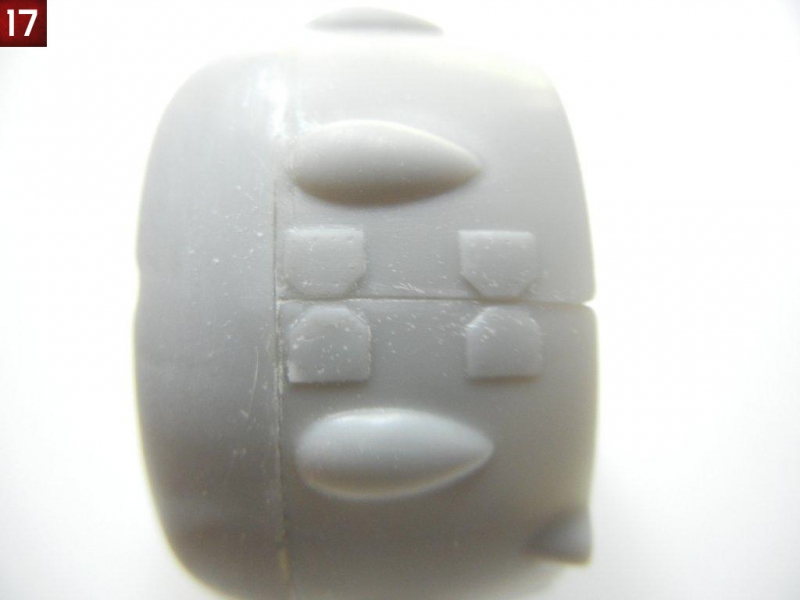
- When dry, you can test fit the upper cowl piece. Mine was too big, so I sanded down each side of the cowl-to-cowl attachment surfaces to the raised bracket points (see photo 17)
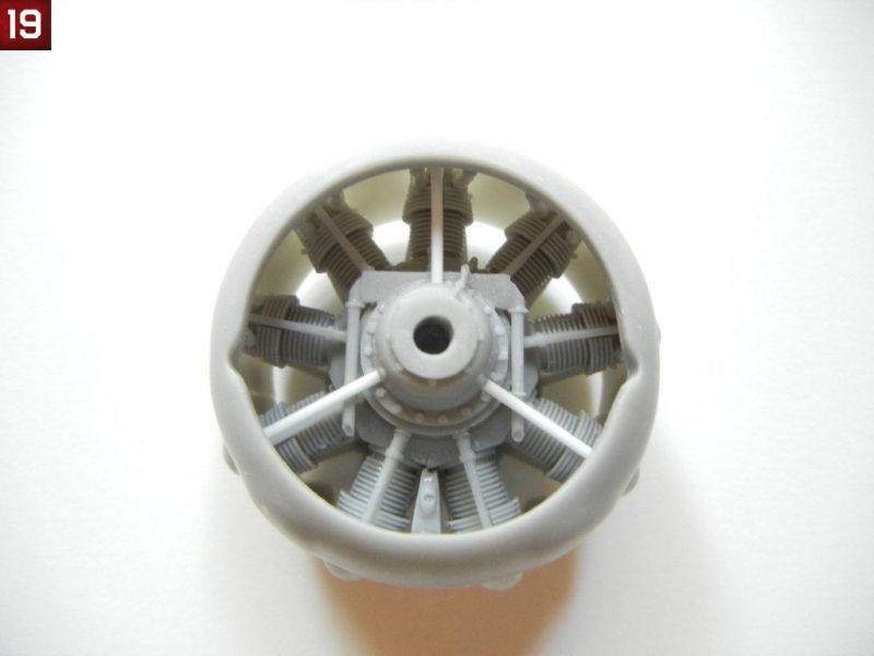
- I then glued one side of the cowl-to-cowl mating surface, let set and then glued the opposite side. I then glued the remaining cowl to exhaust collector ring surface (see photo 18 and 19)
- Attach straps PE16 to each side of the cowl to complete the assembly.
- If desired, you can now paint your cowling and set the completed assembly aside until final assembly
Lower wings
- Drill out the wing strut attachment points using a drilling template (check the "Tips and How To's" section of the Silver Wings website (www.silverwings.pl) for an article on making and using drilling templates).
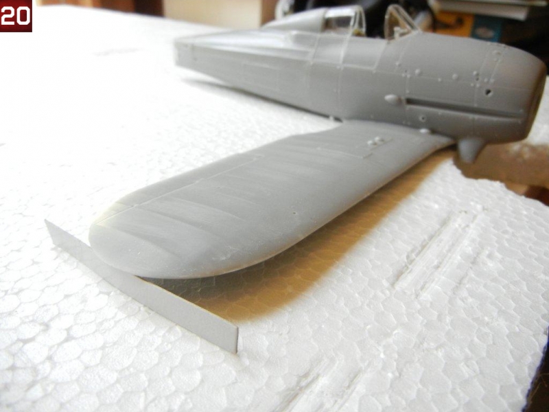
- I placed my model on a piece of styrofoam and gouged out slot for the MG's on the bottom of each wing. Once I had a level surface, I glued the wings to the fuselage, using a 6mm spacer at the tips as indicated in the instructions to achieve the correct dihedral. (see photo 20)
- Attach the anti-skid plates (PE15) to each wing as indicated.
- You can attach the underwing MG barrels, or wait until after painting.
Upper wings
- Before assembling the upper wings, I drilled out the cabane strut holes, and wing strut holes using drilling templates.
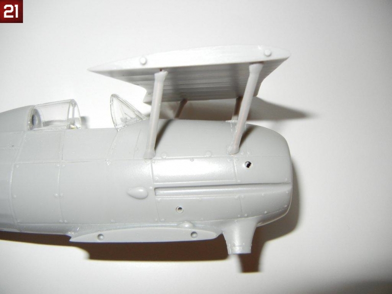
- I test fit the wing center section and cabane struts to the fuselage to ensure a good fit (see photo 21).
- Once satisfied with the fit, remove the wing center section and attach the outer wing sections. Place the wing parts on a flat surface, and glue the wings into position, using a 6mm spacer at the tips as indicated in the instructions to achieve the correct dihedral.
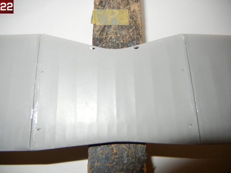
- I had some slight gaps on the bottom of the wing where the center and outer wing parts meet. I filled these with superglue (see photo 22) and sanded smooth once dry.
- I then made a homemade jig (see the Tips & How To's section of the Silver Wings site (www.silverwings.pl) for an article on making your own simple jig) and began the process of attaching the upper wings.
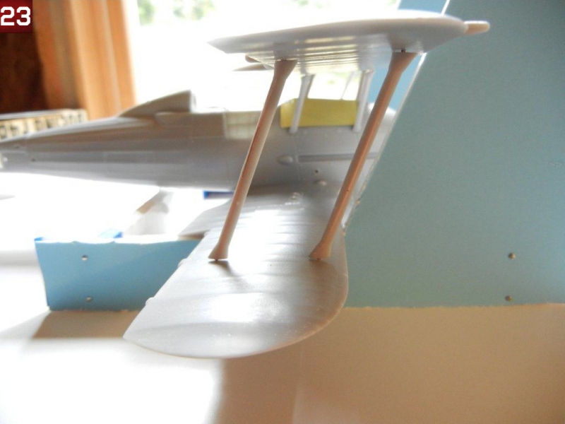
- I sorted out the interplane struts, and found that one pair was ever so slightly longer than the other. As one of the longer pair has a round bump on the front, and the instructions indicate this one goes on the starboard side front, I was able to then sort out which struts went where (the ever so slightly longer ones in front, and the others in the rear). I did note in test fitting that the curve of the resin part of the interplane struts do not match precisely the curve of the wing surfaces (see photo 23).
- Fit each strut to its appropriate position on each mating surface, and trim the brass rod parts to ensure a good fit.
- When ready, mix up some epoxy and start attaching the struts to the fuselage and lower wings in their appropriate positions. When tacky, place the upper wing in position and secure it using your favorite jig to ensure proper alignment.
- Once the epoxy is dry, you can remove the upper wing and clean up any that oozed out where it should not be. At this point, you will want to use your favorite filler as necessary to get a perfect attachment point of the struts to their fuselage and lower wings.
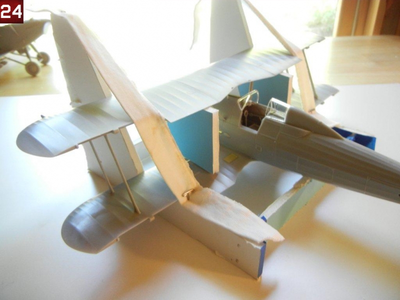
- Once complete, mix up some more epoxy and attach the upper wing, securing it with your favorite jig (see photo 24).
Rear Empennage
The rear empennage for this kit is very straightforward. The kit does provide the rear bell crank for the elevators, which are barely visible on the finished kit, so you should decide if you want to attach any control cables to them. You can also complete this step at any time after you have glued the fuselage together, depending on what you think will be easiest for you and the painting scheme you have chosen.
- Start by attaching the vertical stabilizer to the fuselage.
- Then attach the horizontal stabilizers, ensuring that everything is aligned properly. I noted a tight fit on the port side stabilizer, so I opened the holes slightly to aid in a good fit. Oddly, when I was attaching the horizontal stabilizers, I noticed that if I attached them one way, there was an angle across the backside of them, whereas the other way, the backside was straight. So, be sure to check before gluing that everything is straight.
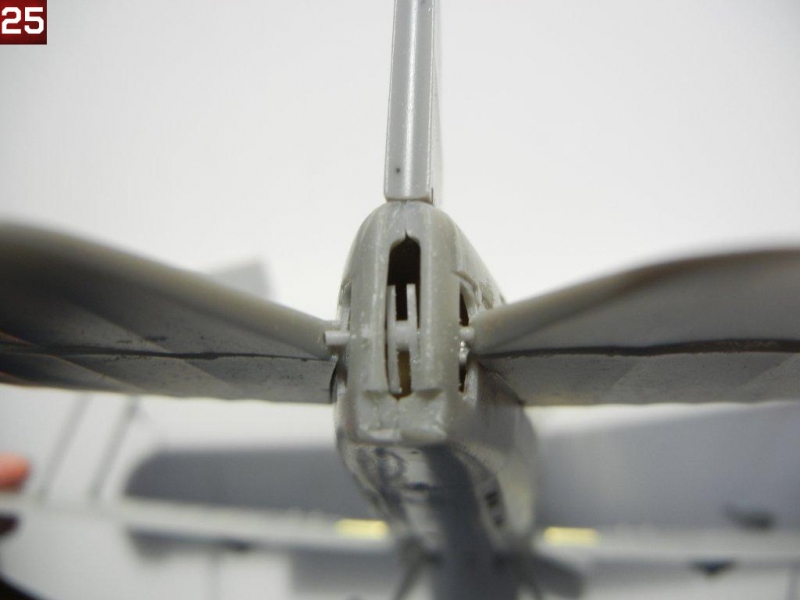
- Now, attach the bell crank assembly to one of the elevators. Test fit to be sure that the bell crank will be more or less centered when looking at them from the slot in the rear. Then test fit to the other elevator, and trim as necessary to get a good fit while keeping them in the proper position. (See photo 25). If you have chosen to attach control cables, this will be an interesting exercise indeed!
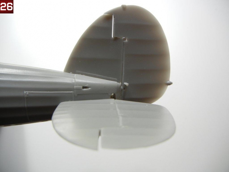
- Attach the control horns to each side of the rudder as indicated in the instructions, and then attach the rudder into position as desired (see photo 26).
Final Assembly
Now we are on the home stretch, and we have a model that looks pretty much like a Gladiator :) You should decide at what point you want to paint (and rig if desired) your model, and stop and do so when you have assembled the necessary parts. Now let's get those final bits attached!
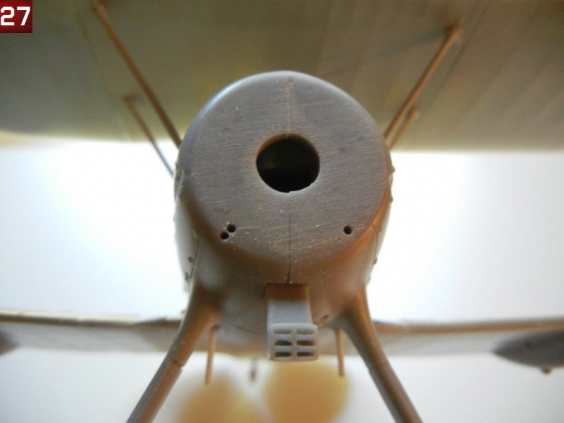
- I started by test fitting the air intake tubes into the holes provided in the front of the fuselage. When I attempted to fit them with the engine/cowl assembly in place, I noticed the holes needed to be relocated, so I noted the correct position and drilled new mounting holes. Photo 27 shows one hole drilled in the proper position (lower and to the outside) on the left, while the two existing holes can be seen as well.
- Next, I glued the main gear legs in position (be sure to select the proper legs for your choice of skis or wheels). I drilled out the mounting hole in the fuselage to make it deeper, and did not trim any of the brass rod to provide maximum strength. You should trim the brass rod where the wheel or skis will attach to ensure a proper fit.
- I attached the step using the three holes indicated in the port-side bottom of the fuselage, and attached the pitot tube to the port side front strut as indicated in the instructions. If your model was equipped with a radio, you can attach the antennae mounting pins on the rudder and upper wings.
- I trimmed 2mm off the attachment point of the carb intake, and glued it in position in the square hole provided in the bottom of the fuselage.
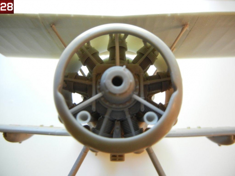
- Now we can attach the engine/cowl assembly to the fuselage. Once positioned, I then attached the two air intake tubes (see photo 28).
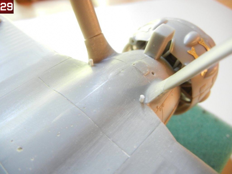
- Now we can attach the exhaust pipes. There is supposed to be a mounting pin towards the rear where the bracket is on the pipes. As this is missing, I needed to make my own. I drilled out the two faint holes in the fuselage at the rear of the main gear struts with a 1mm drill, and inserted two small pieces of the same size styrene rod. I then test fit the exhaust pipes to the cowl and sanded slightly until they were in the correct position (see photo 29).
- You can attach your main wheels and tail wheel (or skis) as indicated in the instructions. Note that the wheels should be attached so that the spot where the remains of the pour bock you removed are at the bottom to ensure the inside detail is in the correct position.
- Attach the wing MG's in place, and attach the appropriate propeller for your model.
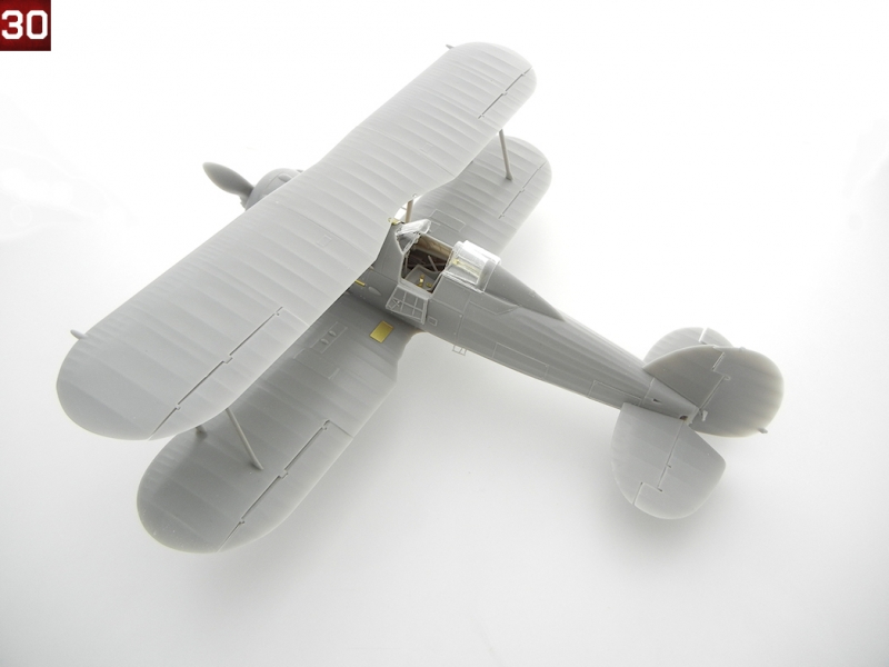
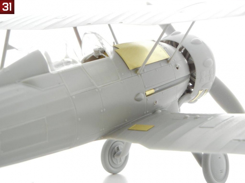
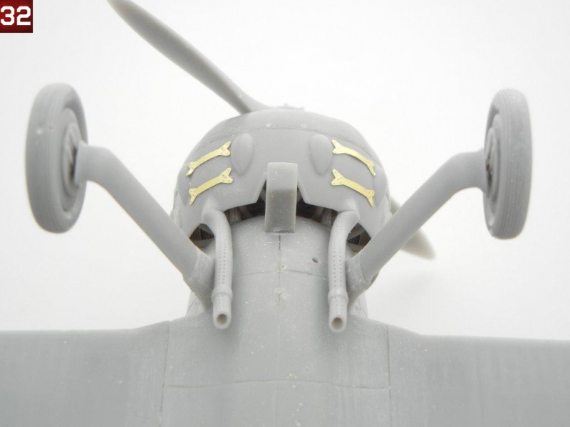
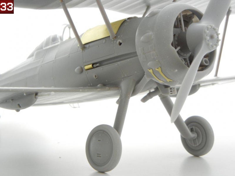
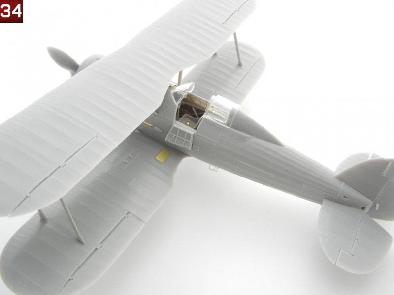
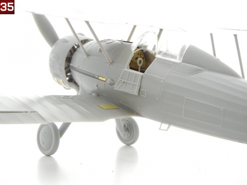
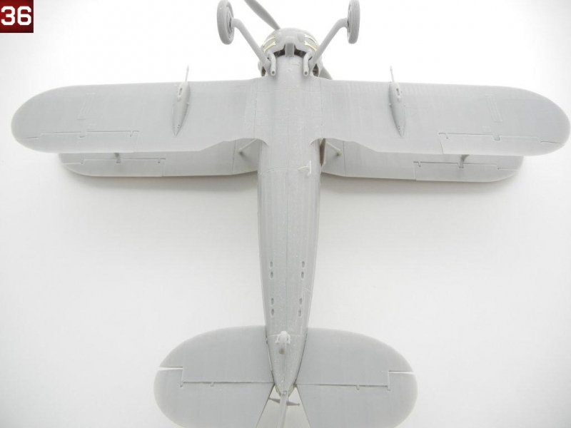
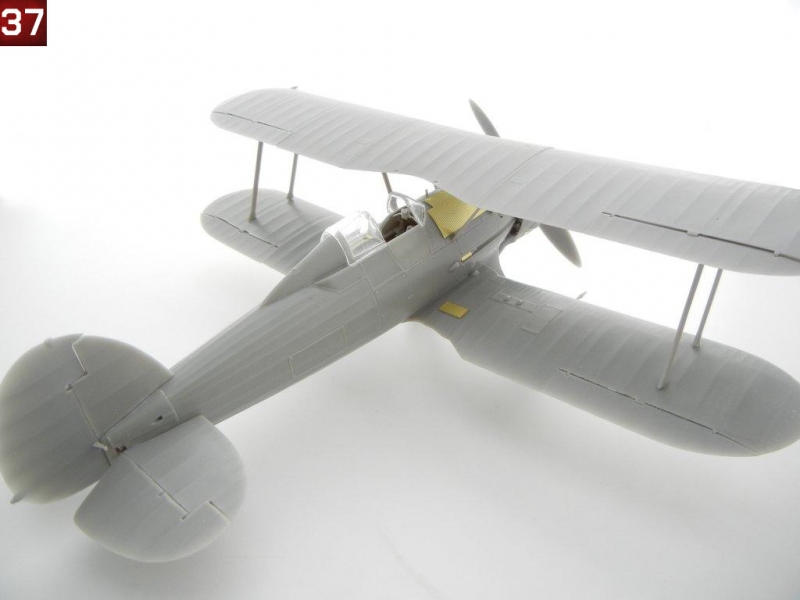
Congratulations on your newly finished model! Photos 30 ~ 37 are of the completed model.
Photos and text copyright Doug Nelson (2012)
Gallery