1:32 Armstrong Whitworth Siskin IIIA
 |
 |
 |
Silver Wings 1:32 Armstrong Whitworth Siskin IIIA build guide
Instructions
Silver Wings has changed the style and format of their instructions. They are now bound along the top edge instead of the side, and have been changed in size to fit the box without folding. For some reason, the traditional numbered steps have also been eliminated. A few notes before you start building:
- Before you join the fuselage together as shown on page 4, you need to skip ahead to page 6 to see what items should be installed on the interior cockpit sides.
- Also on page 4, there seems to be some indication that something is supposed to be installed in the "notch" in the tail before joining the fuselage halves. There is no kit part provided, but it seems there is some sort of hydraulic cylinder there, which you can add from a piece of rod later in the build.
- There is no illustration showing the joining of the two upper wing halves.
Parts Cleanup
As with other Silver Wings kits, parts cleanup is fairly simple, and due to the soft resin they use for their kit, a sprue cutter can even be used to snip most parts from their pour stubs. After that, a few scrapes with the Xacto knife and/or sanding stick and the part is ready for use.
With these kits, since there are no part numbers to worry about, I like to clean up all the parts and then begin the build. Any parts can be painted as appropriate after cleanup and before assembly as well. A few things to note when preparing your kit parts for use:
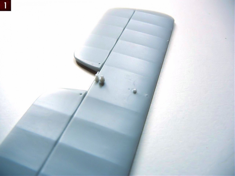
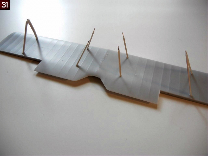
- Use caution in removing the tailplane from the clear plastic bag. It should have 3 pins attached to the bottom (see Photo 1), however 2 were broken off on my kit, but were still in the bag, so I was able to reattach them.
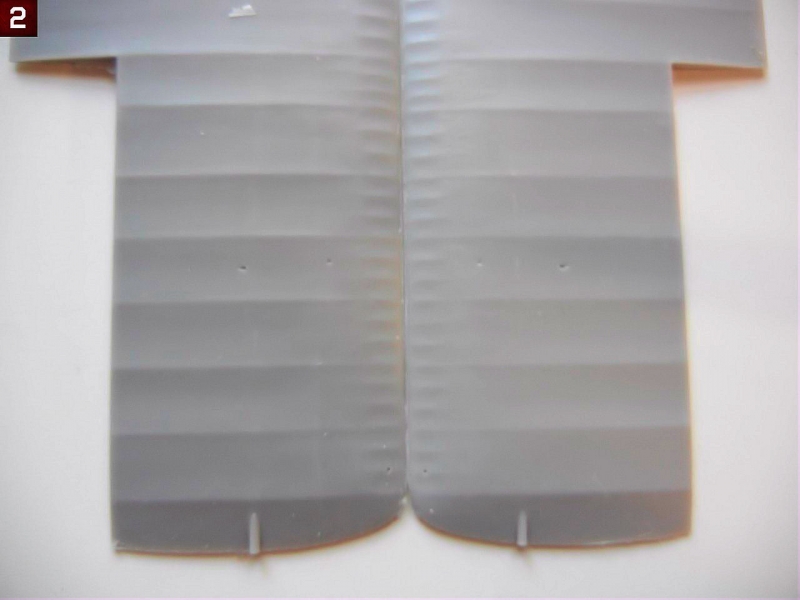
- The wings have excess resin “rods” on the upper tips (see Photo 2), these must be removed as the outer wing should be smooth.
- The mating surfaces on the wing trailing edges and ailerons may require some additional cleanup to get them perfectly straight, test fit the parts as appropriate to see what cleanup may be required.
- Check your fuselage framing for any breaks before you remove the pour blocks. You should repair any breaks with superglue before removing the pour blocks
- If you intend to use the kit provided cockpit frame cross brace tubes, be sure to measure them before you remove them from the pour stubs as I found I had to trim carefully in order to not end up with tubes that were too short.
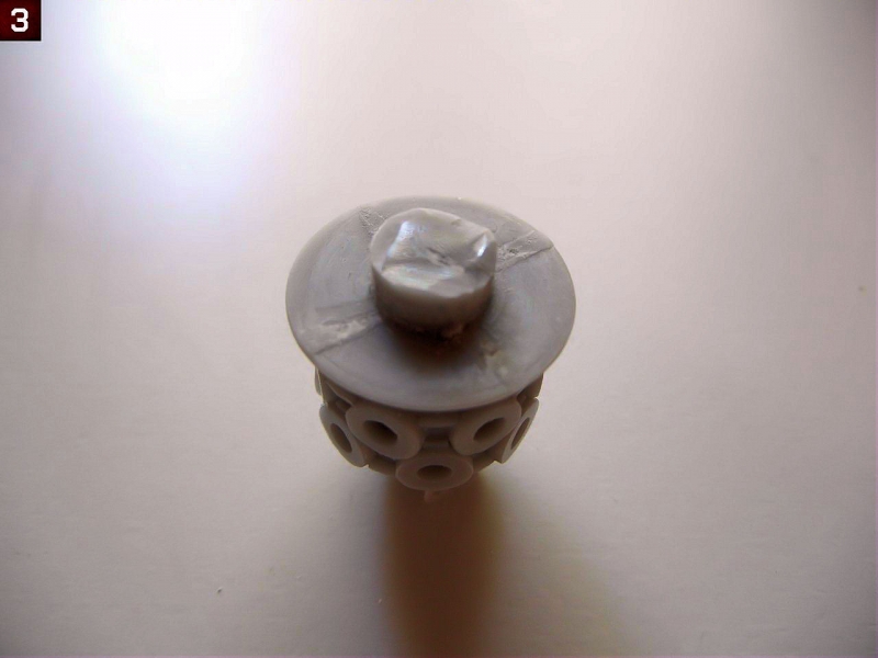
- The engine block has a pour block on the backside, and you should only remove the “fins”, leaving the center round part as this will be needed to attach the engine/cowl assembly to the fuselage. (Photo 3)
- Some of the engine cylinders may have some slight seams on the sides that require cleanup, however any that you "miss" during cleanup will likely not be visible on the finished model without searching really hard for them.
- Test fit your propeller to the engine block and enlarge the hole as necessary to achieve a good fit.
- The seat has a square that sits proud of the seat itself on the underside. This is used for positioning the seat on the support framing and should not be removed. The remaining parts on the bottom of the seat should be removed (although they may look like seat mounting brackets).
Interior Subassemblies
There are a few items that can be assembled before installation in the cockpit, as indicated on page 2 of the instructions. I'll review them here"
- Center Floor Brace (control column/rudder pedals/compass): I used a paintbrush handle to bend the PE rudder straps. Attach the completed rudder pedals to the center floor brace as it will be easier to do so now than after the floor brace is installed in the cockpit frame. Attach the compass as indicated in the instructions, being sure to get it at the proper angle and install the film compass dial after painting. I tried to use my punch set to punch out the compass from the clear film, but the film is somewhat brittle and the printing got damaged doing it that way. The control column should fit onto the flat area in the center rod of the center floor brace as indicated in the instructions with any difficulties. I recommend waiting until after you have the rest of the interior installed before permanently attaching the control column to avoid breaking it. Be sure to install it so that the triggers are on the side facing the seat.
- Instrument Panel: Cut out the instrument backing from the clear film and paint the back white, and install in in position on the PE instrument panel. After assembly, you'll need to paint the back of the panel black as some of it may be seen through the gun troughs if you look hard enough. Also don't forget to cut out and install the "map" provided before installation - I did and it was a a little difficult to get it into position later.
- I recommend leaving the barrels off the machine guns, and installing them after you've assembled and painted the fuselage. This will make it easier to get them into the correct position, and if they are not centered on the breech, it will not be visible. Accordingly, attach the PE parts as indicated to each machine gun breech.
- Wait to assemble the oil cooler until after you have the fuselage completed and painted. You'll need to attach the two posts provided making sure that the attachment bracket detail is oriented the correct way before assembling the PE leaves.
- I recommend leaving the PE propeller blades off the three generators until after they have been test fit to the model.
- I also recommend leaving the shell ejection chutes off the shell ejection ports until they have been installed in the fuselage, and the cockpit with machine guns test fit to ensure proper placement.
- Although not shown on page 2, you should paint the seat and install the PE seatbelts prior to installation (you'll note it magically appears with seatbelts installed on page 3)
Cockpit Assembly
Cockpit assembly starts on page 3 of the instructions. If you've built any other Silver Wings kits, assembly should be familiar to you.
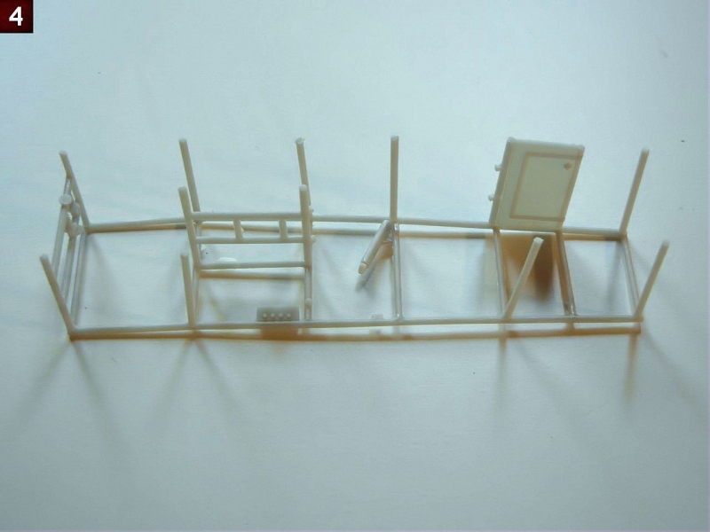
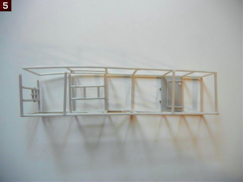
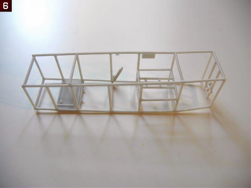
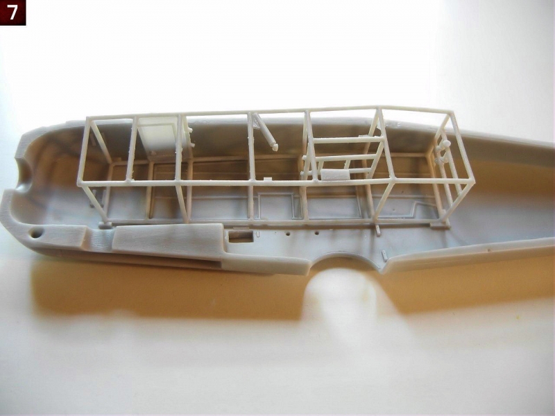
- I started my assembly by cutting the provided resin cross-braces to the appropriate lengths as indicated (you may find it easier to use plastic or metal rod). I then attached the rods, front floorboard and "cat's cradle" to one side of the framing (see Photo 4). I then attached the opposite side framing piece, starting at one end and moving towards the other to ensure the best alignment (see Photo 5/6). Once complete, test fit the frame into the fuselage to be sure everything is lined up properly (see Photo 7).
- Next, attach the heel boards on either side of where the center floor brace will attach Once complete, attach the center floor brace assembly (with rudder pedals and compass) - tabs are provided on both attachment frames to help with alignment. I then attached the seat to the center of the "cat's cradle" and the cylindrical oil(?) tank, trim wheel and throttle control as indicated in the instructions.
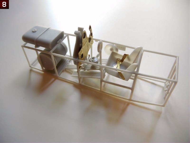
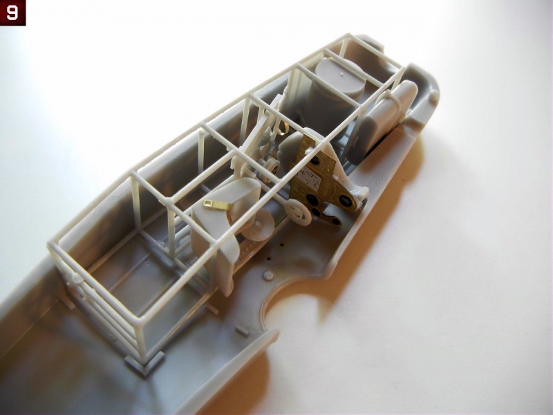
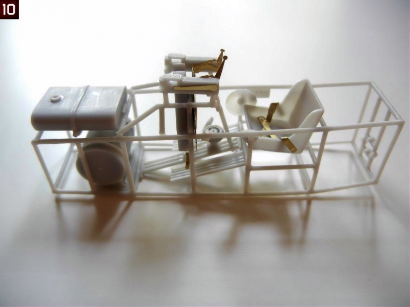
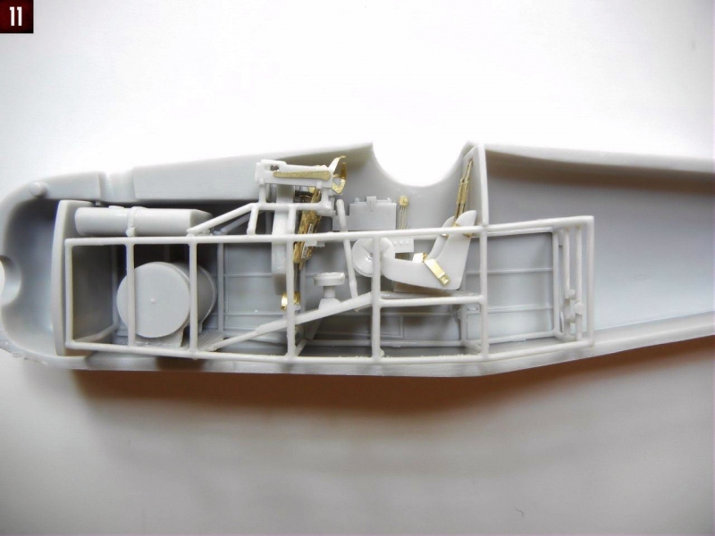
- Attach the fuel tank and the ammo magazine in position as shown (see Photo 8) and test fit the assembly in the fuselage (Photo 9). Now comes the only part that might be challenging, which is attaching the framing that holds the machine guns. First, attach the machine gun breech to the framing part, putting the breech as far towards what will be the rear as possible. I attached them to the position that seems to be indicated in the instructions (see Photo 10) and checked to see that they were approximately 9.5mm apart. Even with this, I found that the breeches of the machine guns were pushed backwards by the area of the fuselage where the guns barrel slots are (see Photo 11). I ended up trimming my fuselage and gun breeches a little in order to improve the fit. You may want to place your framing further towards the rear, so that the first vertical leg is right at the back of the ammo magazine for a better fit. I also had to bend the charging handles down quite a bit so that they cleared the top of the fuselage.
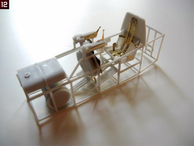
- I folded the shoulder harness as indicated, and attached the backplate on top of the cockpit framework behind the seat as indicated on page 4 of the instructions, and when it was dry, I attached the shoulder harness in the slot (see Photo 12).
Fuselage Assembly
Fuselage assembly is covered on page 4 of the instructions.
- As mentioned previously, jump ahead to page 6 to see what items need to be attached to the fuselage halves before they are joined together. Attach the items as shown. I recommend using PVA or white glue to attach the shell ejection chutes to the shell ejection ports so that you have some flexibility to get them into the correct position to match up the machine gunbreeches when test fitting the completed cockpit.
- There is a PE wiring harness of sorts on the starboard (right) side interior. The instructions show that these wires should be attached to the panel on the cockpit framing directly below it when in position. I recommend that you drill a small hole into the panel for each wire to attach to to ease the placement of the wires. Alternatively, you can simply run the wires behind the panel which also looks fine.
- Test fit, and then glue the forward bulkhead into position on one of the fuselage halves.
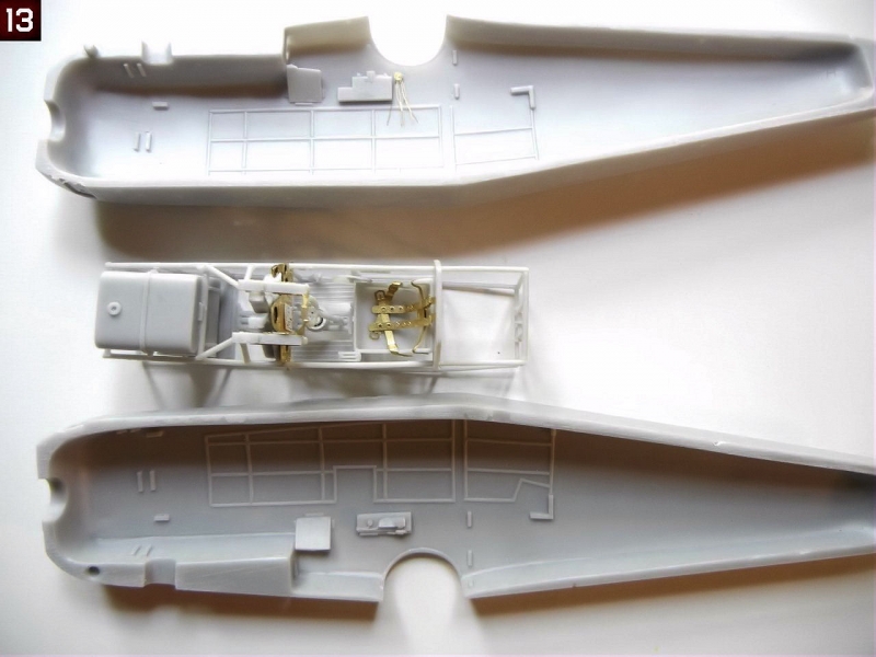
- Install the completed cockpit frame to one of the fuselage halves. Photo 13 shows everything ready to be closed up.
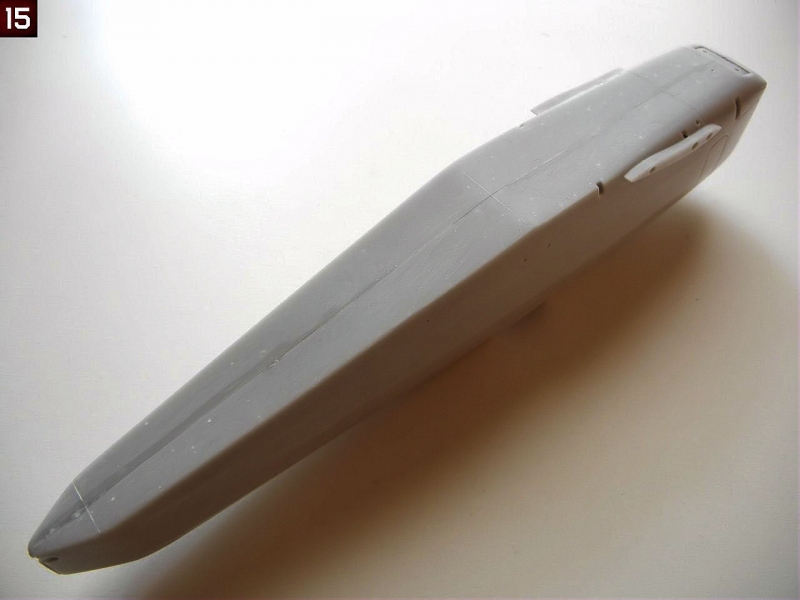
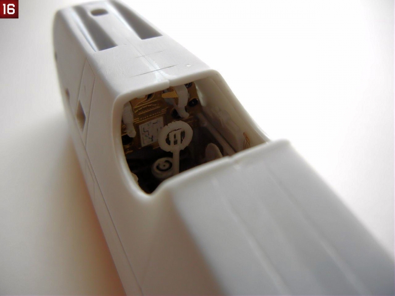
- Glue the fuselage halves together, ensuring the cockpit frame and rear bulkhead are in the correct position. Photos 14~16 show the assembled fuselage.
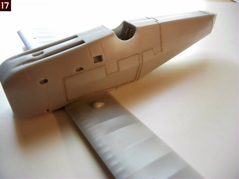
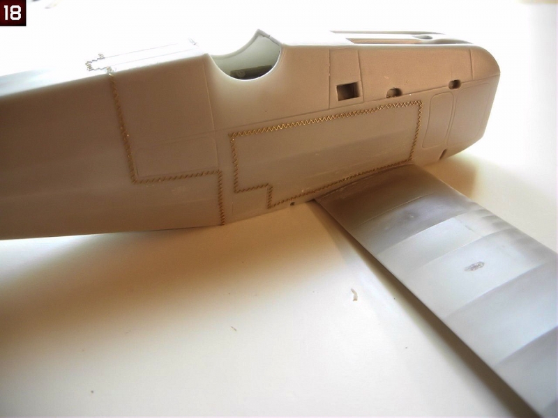
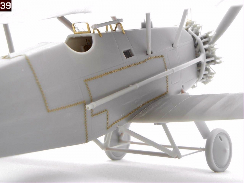
- Once set, attach the PE stitching in the appropriate positions as indicated on page 5 of the instructions. I noted that the stitching for this kit is finer than on previous kits, and bends easier as well. While it may look better, this makes it harder to install in position. Personally, I wish that Silver Wings would simply mold the stitching on the fuselage, leaving these PE parts for the bottom (and top if required) seam as installing them can be a very frustrating exercise. I elected to attach the lower wings prior to the stitching to give myself something to use to hold the model as the stitching tends to come unattached with handling. I recommend applying primer over the stitching as soon as possible to help keep it in place. As an alternative, both Archer transfers and HGW offer alternative, easy to use, decal stitching as well (which I will definitely use on subsequent builds). Photo 17 and 18 show the completed stitching.
- Attach the oval shaped fuel filler to the top of the forward fuselage (page 7).
The following steps are best left for final assembly
- Attach the two machine gun barrels to the machine gun breeches.
- Attach the PE gun sight tube attachments as indicated in on page 7 of the instructions. My references show that the sight should be over the starboard side machine gun trough, so I adjusted the attachment point on the top of the fuselage inward as required to achieve this position. Attach the ring sight in the center of the fuselage as indicated.
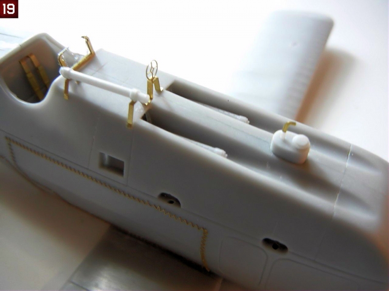
- Build up the windscreen (as shown on page 2 of the instructions) and attach to the fuselage in front to the padded surround. Photo 19 shows the windscreen and gun sights in position.
- Install the fuselage oil cooler brackets to the bottom of the fuselage. I built up the PE oil cooler parts and held them in place with a touch of future. Trim the top of the bracket rods to be just above the last round PE part once complete.
- Attach the generators (shown on page 5) and the gun sights/windscreen until final assembly.
Engine Assembly
Engine assembly is covered in the upper section of page 7 of the instructions, although you can complete this step at any time during the assembly of your model.
The engine of the Siskin is quite visible as there is no cowl, but fortunately Silver Wings gives us a beautiful rendition of the Jaguar III/IV engine. While work on the engine can be repetitious, since you have to do the same thing several times, the results are a worthy engine to be the focal point of the front of your build.
- I began assembly by attaching the back row of cylinders, being sure that each was facing exactly forward.
- Note that when looking at the engine from the front, the left side pushrod is attached to the engine block in front of the right side pushrod. I cut one of the pushrods and test fit it to the engine block/cylinder head in the rear (right side) position and found that it was too long, so I trimmed one to fit, and then made another 6 to match. I then attached all of the rear (right side) pushrods to the engine block/cylinder heads
- I then test fit another pushrod to the left side (front) and trimmed it to fit, and again made 6 to match. I then fit them into position as well. Note that for either side, some pushrods did require slight trimming to ensure a good fit.
- I added the front row of cylinders to the engine.
- Once set, I began attaching the intake pipes which fit to the left side of the cylinder heads (when viewed from the front) and to the mounting base. The longer leg of the intake pipes goes to the front row of cylinders. I had to bend mine slightly together to get the proper fit.
- Once finished, I repeated the process above to attach the pushrods to the front cylinders, again going left over right at the engine block base.
- I added the two parts that go on the top and bottom of the front of the engine block.
- You can attach the two exhaust collectors at this point. When doing so, I suggest test fitting each one and trimming the attachment points as necessary to achieve the best fit. When attaching them, I find it easiest to attach the ends first, and when set, to attach the remaining pipes pushing them into the correct position.
- The two long exhaust pipes provided have small pins on them to help with attachment to the fuselage. I suggest that you temporarily place the engine on the fuselage in order to determine where these contact the fuselage, and drill out small holes. I would then cut off the pins and replace them with some metal or plastic rod, which should make attaching them after the fuselage is painted/decaled easier, as well as make the assembly stronger.
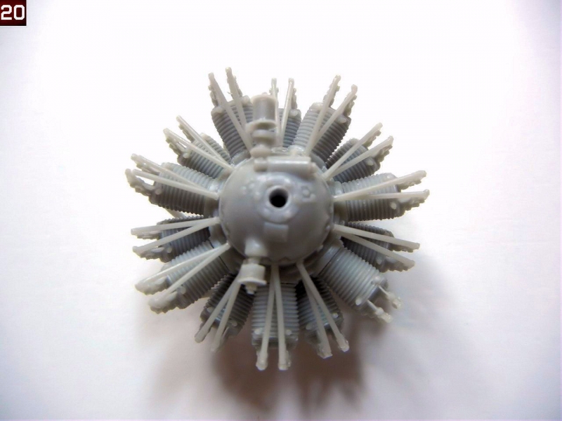
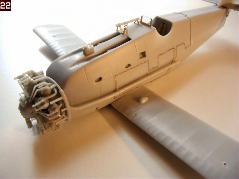
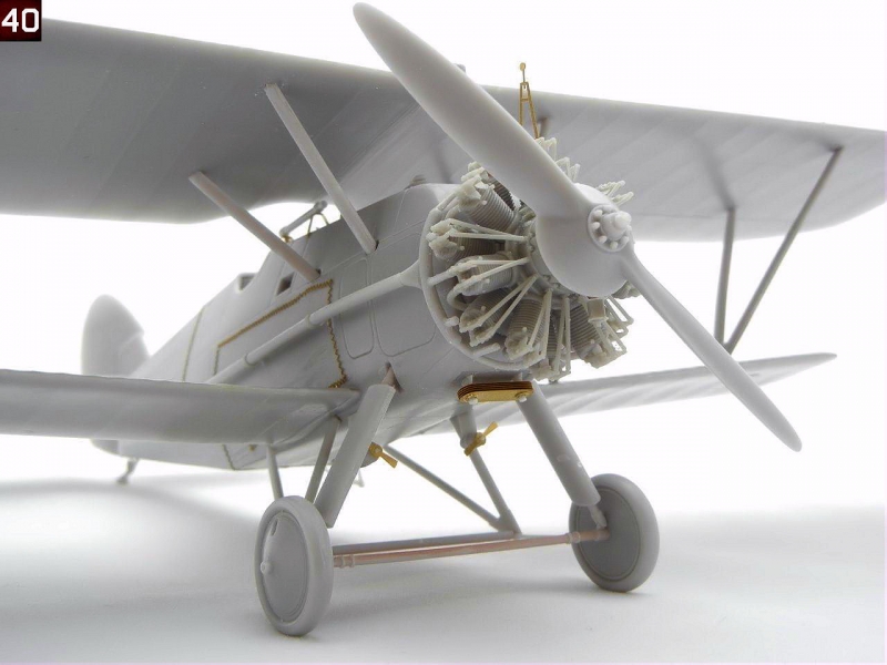
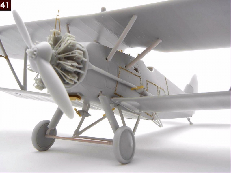
- Photos 20 and 21 show the completed engine. Photo 22 shows the completed engine and exhausts in place on the fuselage.
Lower wings
The lower wings have a metal rod inserted for strength, the remains of which can be used for attaching the lower wings to the fuselage. I recommend drilling out the appropriate hole on each side of the fuselage attachment point to accept the entire metal rod.
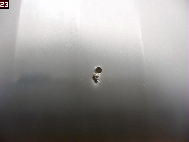
- Begin by drilling out the strut (and rigging if desired) attachment holes in the lower wings as indicated. See the article "Making Templates" in the "Tips and Reviews" section of the Silver Wings website (www.silverwings.pl) for tips on drilling out these holes at the correct angle. Note that when I drilled out the attachment point for the interplane strut, I ended up hitting the metal reinforcement rod (see photo 23). I simply drilled behind it, and thanks to the angle of the protruding strut reinforcement wire, it still fit in the correct position and cover the "mess" completely.
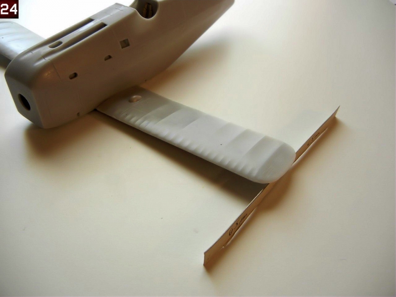
- Attach the wings to the completed fuselage assembly. Note the lower wings should have 6.5mm of dihedral at the tip according to page 6 of the instructions. I use a cardboard spacer to ensure the proper angle (see photo 24).
Rear Empennage
The rear empennage is covered on page 8. As mentioned in the Parts Cleanup section, make sure that your horizontal tailplane has the 3 pins on the bottom, as these will be needed to properly mount it to the fuselage.
- I began by attaching the vertical stabilizer to the horizontal tailplane
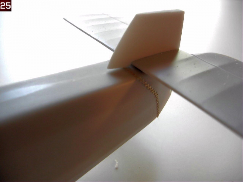
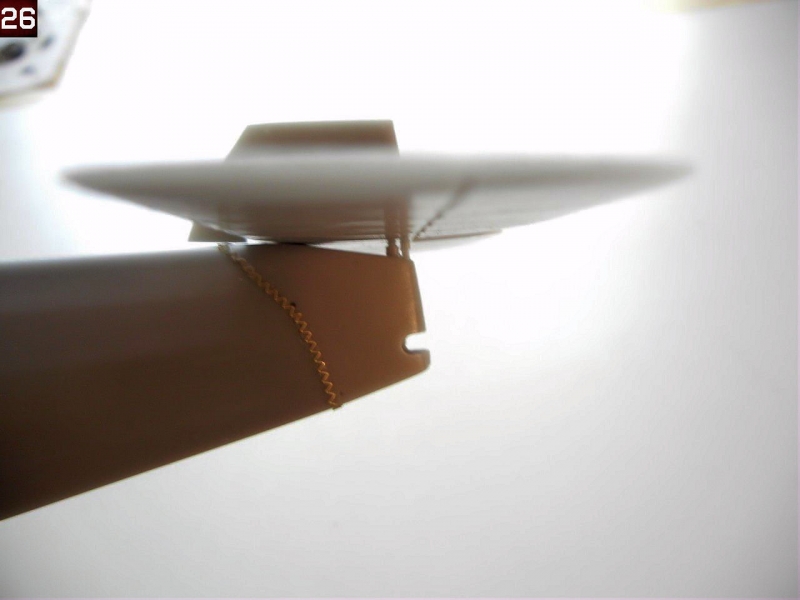
- I then attached the assembly to the fuselage using the 3 pins as indicated in the instructions. Photos 25 and 26 shows the completed assembly attached. Note that the vertical stabilizer should not touch the fuselage.
- You can attach the rudder after it is painted and decaled if you wish.
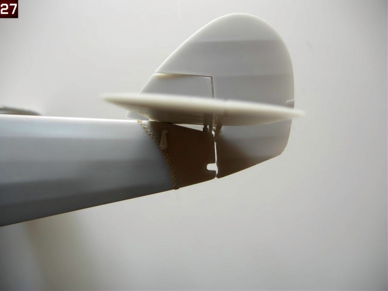
- Attach the control horns to the rudder/vertical stabilizer into glue into position. You can add the small control wire crank and control wires between the fuselage and rudder control horns as shown on page 7 of the instructions during final assembly if desired. Photo 27 shows the completed rear empennage.
Upper wings and wing attachment
The upper wings should have 5mm of dihedral according to the instructions (page 6). Although not show, you will need to join both upper wing halves together. As with the lower wings, I recommend you drill out the appropriate holes for the struts and use the full metal rod if possible to provide extra strength.
- Again, begin by drilling out the holes for the struts (and rigging if desired) in the fuselage and upper wings (see page 8 for proper strut placement).
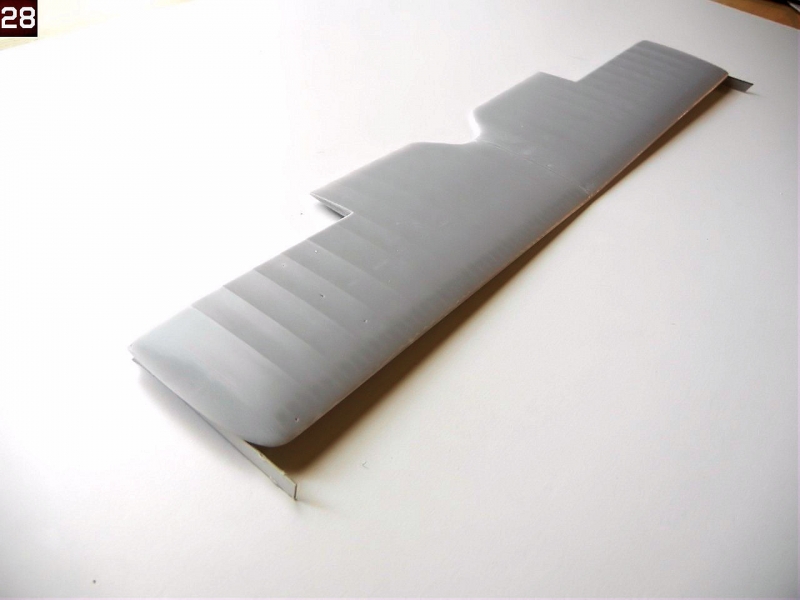
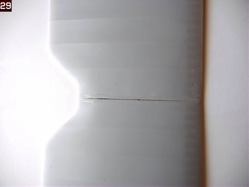
- Test fit the upper wings together and check the dihedral, adjust as necessary (the metal rod can be bent of necessary). When satisfied, glue together (photo 28). I had a slight seam on the upper surface of the join, which was filled with the superglue used to join the wing halves (photo 29).
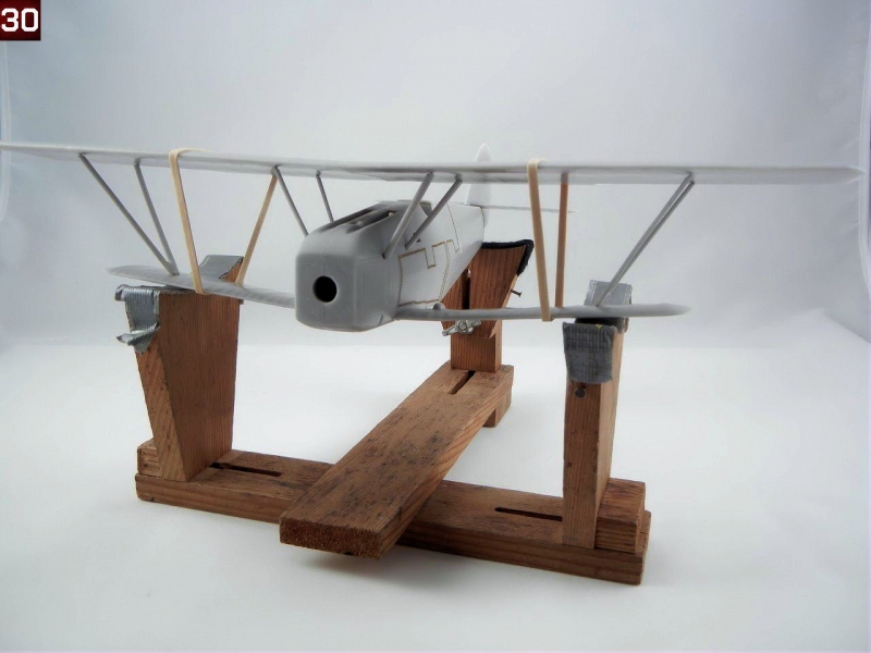
- I test fitted the struts to the upper wing and adjusted the length of the metal rod to achieve the optimal fit. I then test fit the upper wing to the rest of the aircraft, to see if there were any issues I would need to address. Fortunately, there were none, and the fit seemed quite good. Photo 30 shows the test fit (note rubber bands holding everything together).
At this point, you will want to attach the small parts to the upper fuselage and paint/decal your model taking advantage of the ease-of-access before permanently attaching the upper wing once everything is in place.
- When you are ready to attach the upper wing, again test fit to make sure all the struts are in the correct position for optimal fit, and make any final adjustments.
- You may want to use a jig for the remaining steps. See the article "Easy Biplane Jig" in the "Tips and Reviews" section of the Silver Wings website (www.silverwings.pl) to create a simple jig for aligning your wings.
- This time, I decided to attach the interplane and cabane struts to the bottom of the upper wing using slow setting superglue (Photo 31).
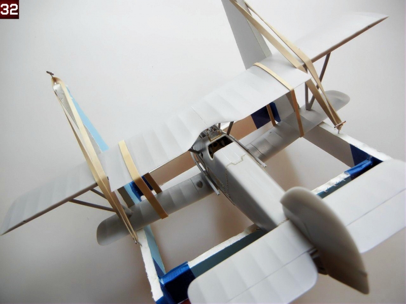
- I then immediately used the same slow setting superglue to begin attaching the struts to the main assembly, starting with the cabane struts, and finishing with the interplane struts. I then placed the model into the jig to make sure the wings were properly aligned (Photo 32).
Main Landing Gear
The main gear appears complex, but it is fairly easy to attach correctly. For the purposes of this Build Guide, we'll separate the main gear assembly into two parts, the rear support structure, and the main axel.
- Test fit the two "V" shaped support structure braces into the slots on eh bottom of the fuselage, as indicated on page 9 of the instructions. You will need to trim the resin "pins" on the end of the support legs to achieve the optimal fit. Test fit the cross brace, and trim the brass rod so that only a slight amount shows when inserted into the holes in the "V" shaped support struts (this slight amount of brass rod is where we will attach the braces that connect the support structure to the main axel). Attach the support structure "V" braces to the fuselage, trapping the cross brace between them.
- Test fit the main axel legs (with the shock covers on them) to the fuselage as indicated on page 9, placing the main axel between them, using the mounting flange on the main axel to ensure proper positioning.
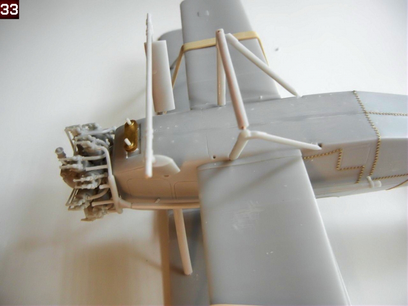
- Attach the main axel legs using slow setting superglue or epoxy, and attach the main axel to them (photo 33 shows the assembly thus far).
- Attach the small connecting rods to the rear support structure, using the space with the brass rod showing on the cross brace.
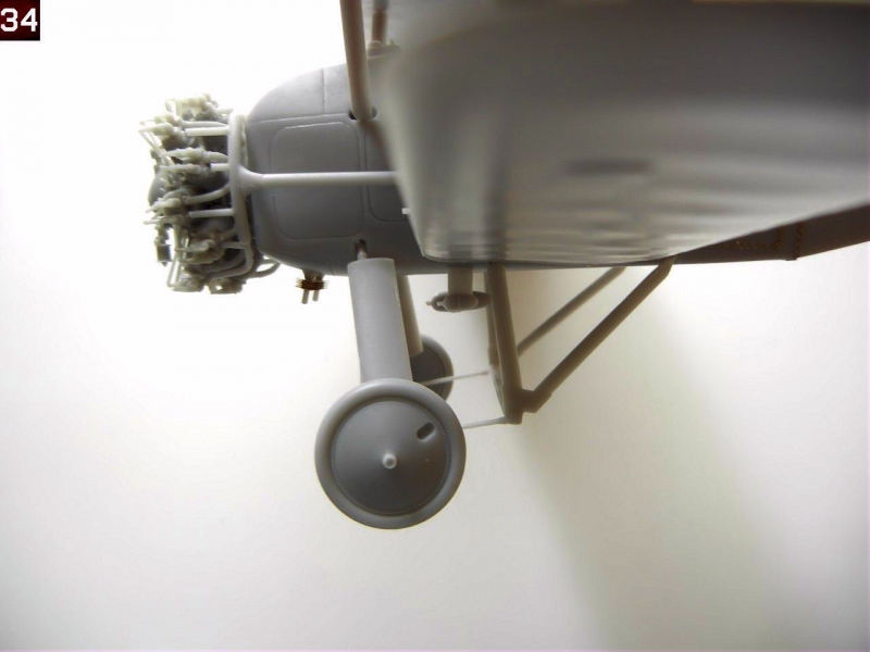
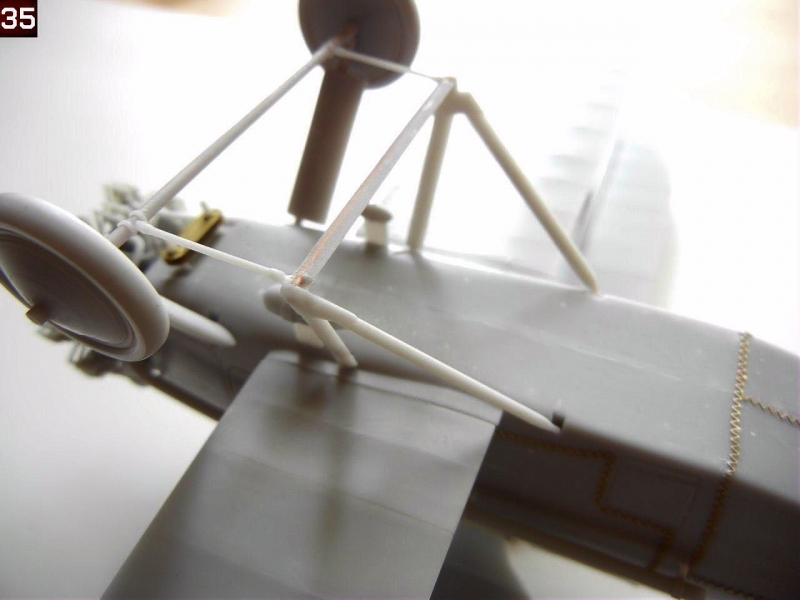
- Pull back the main gear to meet the connecting rods and glue in place. Photo 34 shows the rearward angle of the completed gear for reference.
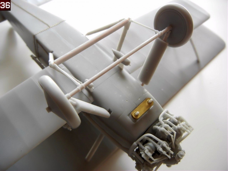
- Attach the main wheels when dry. Photos 35 and 36 show the completed landing gear assembly.
Final Assembly
- Page 10 provides the rigging and control cable installation guides.
- Attach the gun barrels, gun sights, windscreen oil cooler and generators as discussed in the fuselage assembly section above.
- Attach the engine, and long exhaust pipes, as well as the PE structure that attaches to the top cylinder.
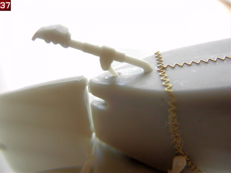
- Attach the tail skid to the bottom of the rear fuselage using the holes provided. On my example, the rear attachment rod was missing (and on my other two kits), so I made one from a piece of plastic rod (see Photo 37).
- Attach the control cable support guides into position on the ailerons of the top wings. If you are going to attach the control cables, Silver Wings has molded pre-sunk holes for the cables in the wings and ailerons.
- Attach the lights on the wing tips and center of the wing.
- If your model was equipped with a radio, make two aerial posts out of .020 plastic rod, and attach to the upper wing in the holes provided (drill out for a better fit). Also attach the aerial post on the fuselage behind the cockpit. If your model was not equipped with a radio, you'll want to fill the holes.
- Finally, attach the pitot to the forward starboard interplane strut.
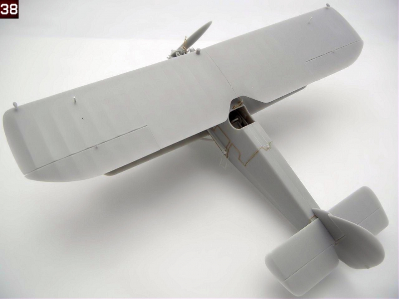
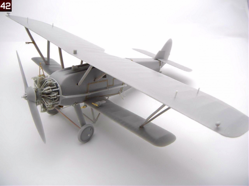
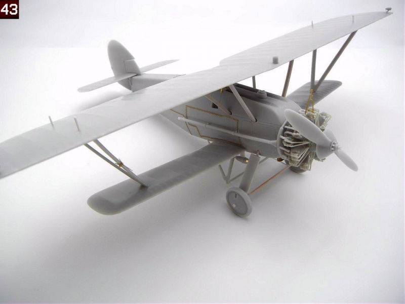
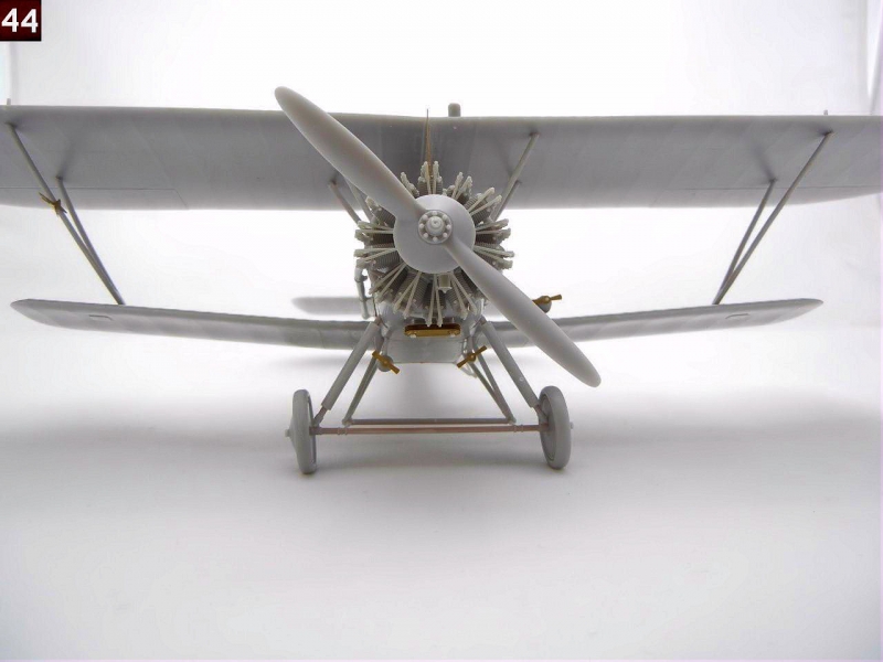
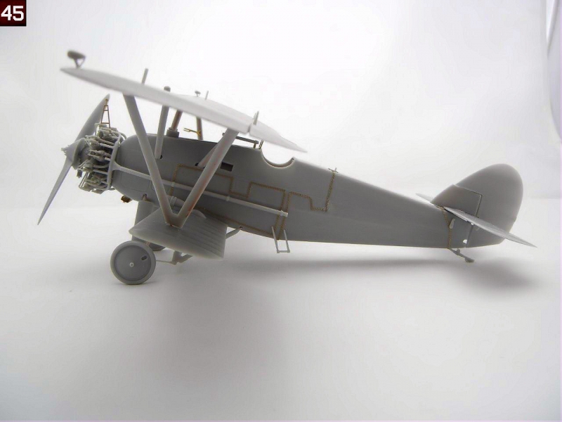
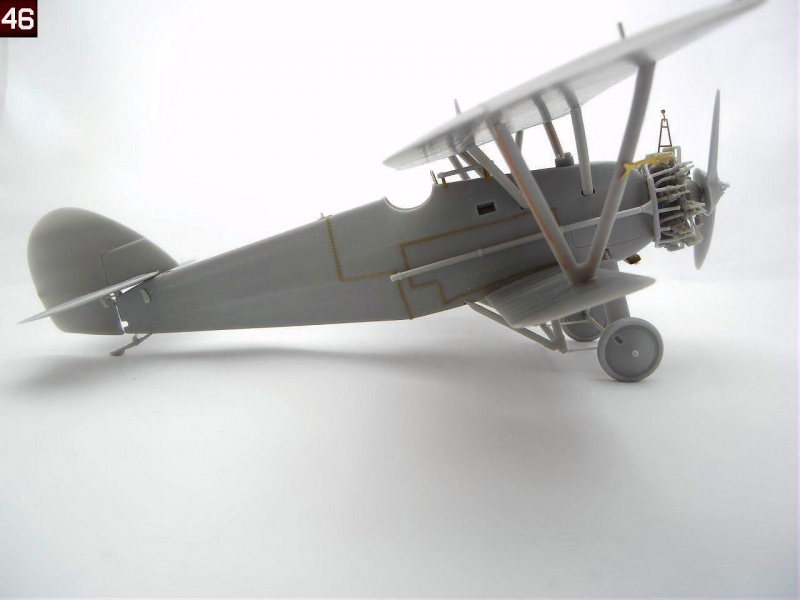
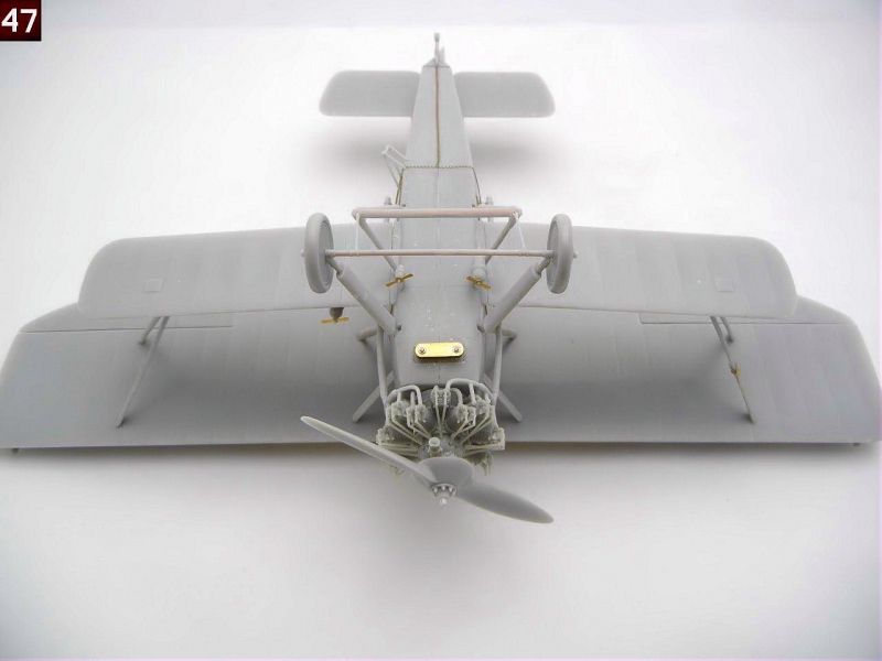
Congratulations on your newly finished model! Photos 38 ~ 47 are of the completed model.
Photos and text copyright Doug Nelson (2012)
Gallery